


T
T
T
S
S
S
1
1
1
6
6
6
G
G
G
~
~
~
6
6
6
4
4
4
G
G
G
C
C
C
F
F
F
4
4
4
0
0
0
0
0
0
400X CompactFlash Card
Transcend Information Inc.
V1.0
37
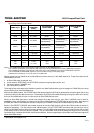
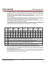
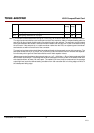
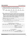
Name
Comment Min
[V/ns]
Max
[V/ns]
Notes
S
RISE
Rising Edge Slew Rate for any signal
1.25 1
S
FALL
Falling Edge Slew Rate for any signal
1.25 1
Note: 1) The sender shall be tested while driving an 18 inch long, 80 conductor cable with PVC insulation material.
The signal under test shall be cut at a test point so that it has not trace, cable or recipient loading after the
test point. All other signals should remain connected through to the recipient. The test point may be located
at any point between the sender’s series termination resistor and one half inch or less of conductor exiting
the connector. If the test point is on a cable conductor rather than the PCB, an adjacent ground conductor
shall also be cut within one half inch of the connector.
The test load and test points should then be soldered directly to the exposed source side connectors. The
test loads consist of a 15 pF or a 40 pF, 5%, 0.08 inch by 0.05 inch surface mount or smaller size capacitor
from the test point to ground. Slew rates shall be met for both capacitor values.
Measurements shall be taken at the test point using a <1 pF, >100 Kohm, 1 Ghz or faster probe and a 500
MHz or faster oscilloscope. The average rate shall be measured from 20% to 80% of the settled VOH level
with data transitions at least 120 nsec apart. The settled VOH level shall be measured as the average
output high level under the defined testing conditions from 100 nsec after 80% of a rising edge until 20% of
the subsequent falling edge.