


T
T
T
S
S
S
8
8
8
G
G
G
~
~
~
1
1
1
6
6
6
G
G
G
C
C
C
F
F
F
6
6
6
0
0
0
0
0
0
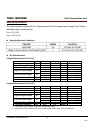
600X CompactFlash Card
Transcend Information Inc.
V1.0
17
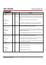
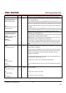
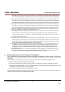
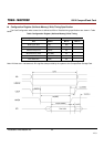
Signal Interface
Electrical specifications shall be maintained to ensure data reliability. Additional requirements are necessary for
Advanced Timing Modes and Ultra DMA modes operations. See next sections for additional information.
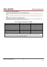
Item Signal Card
10
Host
10
Control Signal
-CE1
-CE2
-REG
-HIOE
-IOWR
Pull-up to V
CC
500 K R 50 K and
shall be sufficient to keep inputs inactive
when the pins are not connected at the
host.
1
-OE
-WE
Pull-up to V
CC
500 K R 50 K .
1,2
RESET
Pull-up to V
CC
500 K R 50 K .
1,2,9,
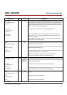
Status Signal
READY
-WAIT
WP
Pull-up to V
CC
R 10 K .
3
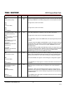
-INPACK
In PCMCIA PC Card modes Pull-up to V
CC
R 10 K .
4
In True IDE mode, if DMA operation is
supported by the host, Pull-down to
Gnd R
5.6 K .
5
PC Card / True IDE hosts switch the pull-
up
to pull down in True IDE mode if DMA
operation is supported.
The PC Card mode Pull-up may be left
active during True IDE mode if True IDE
DMA operation is not supported.
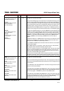
Address
A[10:00]
-CSEL
Data Bus D[15:00]
1.
Card Detect
-CD[2:1]
Connected to GND in the card
Voltage Sense
-VS1
-VS2
Pull-up to Vcc 10 K R 100K .
Battery/Detect BVD[2:1]
Pull-up R 50 K .
3.6
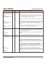
Notes: 1) Control Signals: each card shall present a load to the socket no larger than 50 pF
10
at a DC current of 700 A
low state and 150 A high state, including pull-resistor. The socket shall be able to drive at least the following
load
10
while meeting all AC timing requirements: (the number of sockets wired in parallel) multiplied by (50 pF
with DC current 700 A low state and 150 A high state per socket).
2) Resistor is optional.
3) Status Signals: the socket shall present a load to the card no larger than 50 pF
10
at a DC current of 400 A low