


T
T
T
S
S
S
8
8
8
G
G
G
~
~
~
1
1
1
6
6
6
G
G
G
C
C
C
F
F
F
6
6
6
0
0
0
0
0
0
600X CompactFlash Card
Transcend Information Inc.
V1.0
31
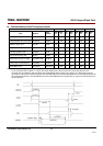
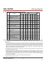
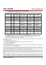
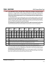
True IDE Ultra DMA Mode Read/Write Timing Specification
Ultra DMA operations can take place in any of the three basic interface modes: PC Card Memory mode, PC Card I/O
mode, and True IDE (the original mode to support UDMA). The usage of signals in each of the modes is shown in Table
24:Ultra DMA Signal Usage In Each Interface Mode
UDMA Signal
Type
Pin # (Non
UDMA MEM
MODE)
PC CARD MEM
MODE UDMA
PC CARD IO MODE
UDMA
TRUE IDE MODE
UDMA
DMARQ Output
43 (-INPACK) -DMARQ -DMARQ DMARQ
HREG Input
44 (-REG) -DMACK DMACK -DMACK
HIOW Input
35 (-HIOW) STOP 1 STOP 1 STOP 1
HIOE Input
34 (-HIOE)
-HDMARDY(R)
1
,
2HSTROBE(W)
1, 3, 4
-HDMARDY(R)
1, 2
HSTROBE(W)
1, 3, 4
-HDMARDY(R)
1, 2
HSTROBE(W)
1, 3, 4
IORDY Output
42 (-WAIT)
-DDMARDY(W)
1, 3
DSTROBE(R)
1. 2. 4
-DDMARDY(W)
1, 3
DSTROBE(R)
1. 2. 4
-DDMARDY(W)
1, 3
DSTROBE(R)
1. 2. 4
HD [15:0] Bidir
… (D[15:00]) D[15:00] D[15:00] D[15:00]
HA [10:0] Input
… (A[10:00]) A[10:00] A[10:00] A[02:00] 5
CSEL Input
39 (-CSEL) -CSEL -CSEL -CSEL
HIRQ Output
37 (READY) READY -INTRQ INTRQ
CE1
CE2
Input
7 (-CE1)
31 (-CE2)
-CE1
-CE2
-CE1
-CE2
-CS0
-CS1
Notes:1) The UDMA interpretation of this signal is valid only during an Ultra DMA data burst.
2) The UDMA interpretation of this signal is valid only during and Ultra DMA data burst during a DMA Read command.
3) The UDMA interpretation of this signal is valid only during an Ultra DMA data burst during a DMA Write command.
4) The HSTROBE and DSTROBE signals are active on both the rising and the falling edge.
5) Address lines 03 through 10 are not used in True IDE mode.
Several signal lines are redefined to provide different functions during an Ultra DMA data burst. These lines assume their
UDMA definitions when:
1 an Ultra DMA mode is selected, and
2 a host issues a READ DMA, or a WRITE DMA command requiring data transfer, and
3 the device asserts (-)DMARQ, and
4 the host asserts (-)DMACK.
These signal lines revert back to the definitions used for non-Ultra DMA transfers upon the negation of -DMACK by the
host at the termination of an Ultra DMA data burst.
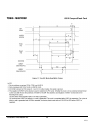
With the Ultra DMA protocol, the STROBE signal that latches data from D[15:00] is generated by the same agent (either
host or device) that drives the data onto the bus. Ownership of D[15:00] and this data strobe signal are given either to the
device during an Ultra DMA data-in burst or to the host for an Ultra DMA data-out burst.
During an Ultra DMA data burst a sender shall always drive data onto the bus, and, after a sufficient time to allow for
propagation delay, cable settling, and setup time, the sender shall generate a STROBE edge to latch the data. Both
edges of STROBE are used for data transfers so that the frequency of STROBE is limited to the same frequency as the
data.
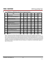
Words in the IDENTIFY DEVICE data indicate support of the Ultra DMA feature and the Ultra DMA modes the device is
capable of supporting. The Set transfer mode subcommand in the SET FEATURES command shall be used by a host to
select the Ultra DMA mode at which the system operates. The Ultra DMA mode selected by a host shall be less than or