


Unibrain Fire-i 501/511/601/701/702/810 Operation Manual Page 3
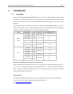
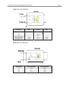
1.2.2. Trigger Connector Port
The External Trigger Connector provides the access to multiple I/O and also provides power as a secondary source.
The trigger pin layout differs depending on the model:
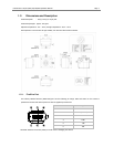
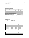
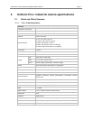
A) Fire-i 501/511/601:
Pin Signal Pin Signal
1 Power GND 7 Tx RS232
2 Ext. Power (+12V) 8 GND
3 GND 9 NC
4 NC 10 Ext. Trigger
5 GND 11 Strobe
6 Rx RS232 12 GND
Note: NC pins must have no connection
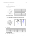
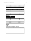
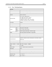
B) Fire-i 701/702/810 (models with optocoupler – September 2007 production or newer)
Pin Signal Pin Signal
1 Power GND 7 GND
2 Ext. Power(+12v) 8 Rx RS232
3 GND 9 Tx RS232
4 Ext. Trigger 10 NC
5 Ext. Trigger GND 11 Strobe
6 NC 12 Strobe Power
Note: NC pins must have no connection. Changes in pin assignment from older models are indicated with blue color.
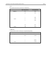
1.2.3. Status LED
LED Status Isochronous Channel Packet Transfer
RED Disable NO
GREEN Enable Flicker
OFF Enable NO
Note: When power off, LED is OFF
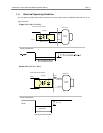
1.2.4. Camera Power Requirement
The cameras utilize a selection of power among the firewire bus and Trigger Connector Port where power source with
higher voltage provides the power to the camera. Input voltage range or 8V ~ 30V is accepted.