


VIVOTEK
User's Manual - 7
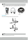
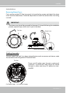
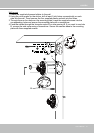
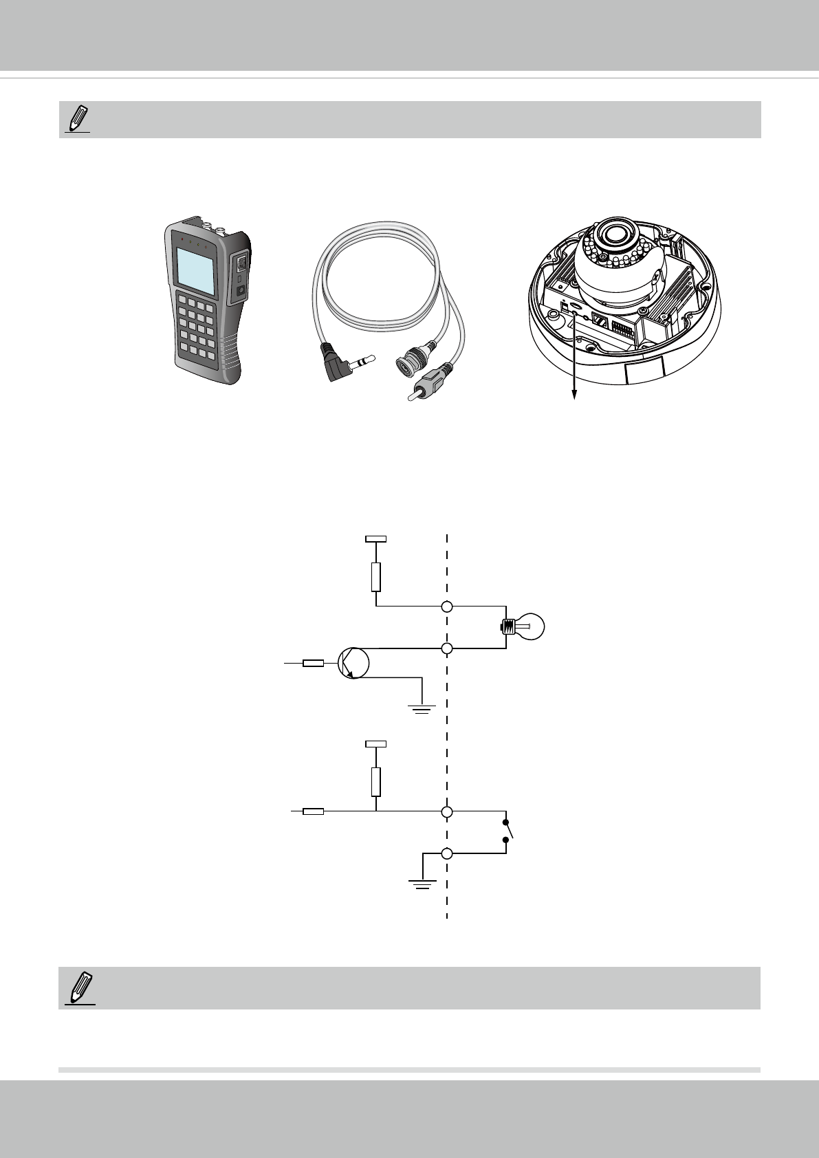
DI/DO Diagram
Please refer to the following illustration for the connection method.
12V
+12V
Digital output-
PIN 1
Power+12V
PIN 2
Digital input
PIN 3
DI-: Common Ground
PIN 6
NOTE:
The maximum output load from pins #1 & 2 is 50mA.
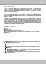
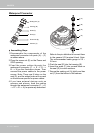
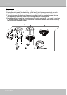
1. There is no internal microphone. Connect an external microphone if you need audio inputs.
2. Use the included AV cable to connect to a camera tester or LCD monitor to begin initial
setup.
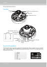
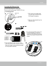
NOTE:
LCD Monitor/
Camera tester
AV Out