


VIVOTEK - A Leading Provider of Multimedia Communication Solutions
User's Manual - 5
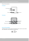
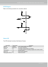
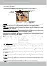
DI/DO Diagram
Refer to the following illustration for connection method�
5V
+5V
Digital output
PIN 1
Power+5V
PIN 2
Digital input
PIN 3
Ground
PIN 4
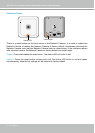
Status LED
The LED indicates the status of the Network Camera�
Status LED Privacy button Description
Solid red Solid blue Power is being supplied to the camera�
Blinking red Blinking blue The camera is booting up�
Solid red OFF The camera is trying to obtain an IP address�
Blinking green OFF
An IP address has been successfully assigned to the camera and the
camera is working�
Blinking red OFF During firmware upgrading�
Blinking green and red OFF Restore the camera�