English English
10 © Titan Tool Inc. All rights reserved.
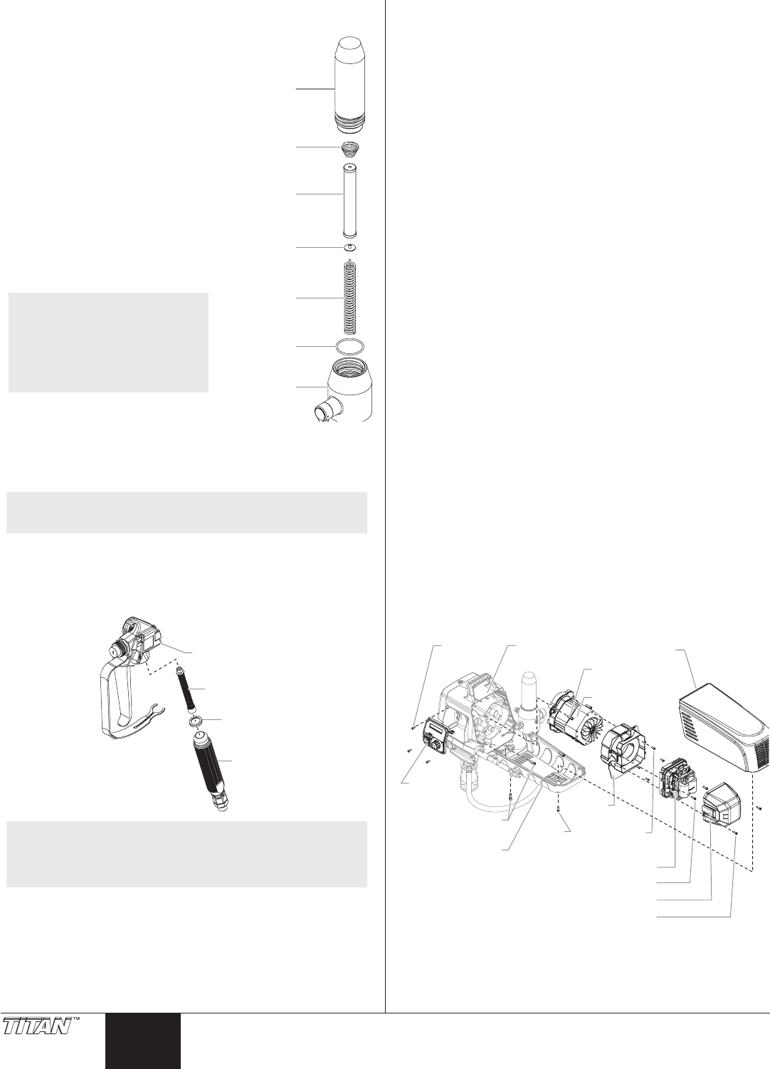
Replacing the Filters
Pump Filter
Filter Body
Filter Spring
Filter Spring
Adapter
Core Spring
Filter
O-ring
ilter Housing
1. Loosen and remove the lter
body by hand.
2. Slip the lter o of the core
spring.
3. Inspect the lter. Based on
inspection, clean or replace the
lter.
4. Inspect the o-ring. Based on
inspection, clean or replace the
o-ring.
5. Slide the new or cleaned lter
over the core spring with the
lter spring adapter in place.
Push the lter into the center of
the lter housing.
6. Slide the lter body over the
lter and thread it into the lter
housing until secure.
NOTE: The lter housing
should be hand-
tightened, but make
sure the lter housing
is seated fully into the
pump block.
Gun Filter
1. Move the gun trigger lock to the unlocked position.
2. Loosen and remove the handle from the gun body.
3. Turning clockwise, unscrew the lter from the gun body.
NOTE: Left-handed threads require turning the lter
clockwise to remove.
4. Turning counterclockwise, screw the new or cleaned lter into
the gun body.
5. Make sure the handle seal is in position and thread the handle
into the gun body until secure.
6. Move the gun trigger lock to the locked position.
Handle
Seal
Filter
Gun
Body
NOTE: For more detail, part number information, and
complete assembly drawings, please see the LX-80II
Professional Airless Gun Owner’s Manual (P/N 313-
2293).
Replacing the Motor Assembly
1. Unplug the unit.
2. Loosen and remove the two (2) motor shroud screws. Remove
the motor shroud.
3. Loosen and remove the three (3) belly pan screws. Remove
the belly pan.
4. Loosen and remove the two (2) motor cover screws. Remove
the motor cover.
5. Disconnect all wires between the motor and the sprayer.
6. Loosen and remove the four (4) control panel screws. Remove
the control panel.
7. Disconnect the wires between the motor and the control
panel.
8. Loosen and remove the two (2) motor controller screws.
Remove the motor controller.
9. Loosen and remove the four (4) motor bae screws. Remove
the motor bae.
10. Loosen and remove the three (3) motor mounting screws.
11. Pull the motor out of the gearbox housing.
12. With the motor removed, inspect the gears in the gearbox
housing for damage or excessive wear. Replace the gears, if
necessary.
13. Install the new motor into the gearbox housing.
14. Secure the motor with the three (3) motor mounting screws.
15. Reconnect the wires between the sprayer and the new motor.
(refer to the electrical schematic in the Parts List section of this
manual).
16. Place the bae over the end of the motor assembly. Secure
with the four (4) motor bae screws.
17. Place motor controller back into place behind the motor
bae. Secure with the two (2) motor controller screws.
18. Reconnect all wires between the motor and sprayer.
19. Reconnect the wires between the motor and the control
panel.
20. Replace control panel and secure with four (4) control panel
screws.
21. Place the motor cover back over the motor controller. Secure
with the two (2) motor cover screws.
22. Put the belly pan back in place and secure with the three (3)
belly pan screws.
23. Slide the motor shroud over the motor assembly.
24. Secure the motor shroud with the two (2) motor shroud
screws.
Motor
Shroud
Screw
Motor Cover
Motor Cover Screw
Motor Controller Screw
Motor Controller
Motor Bae
Screw
Motor
Bae
Motor Shroud
Motor Mounting
Screw
housing
Panel
Screw
Motor
Belly Pan
Screw
Belly Pan
Control
Panel
