English English
© Titan Tool Inc. All rights reserved. 11
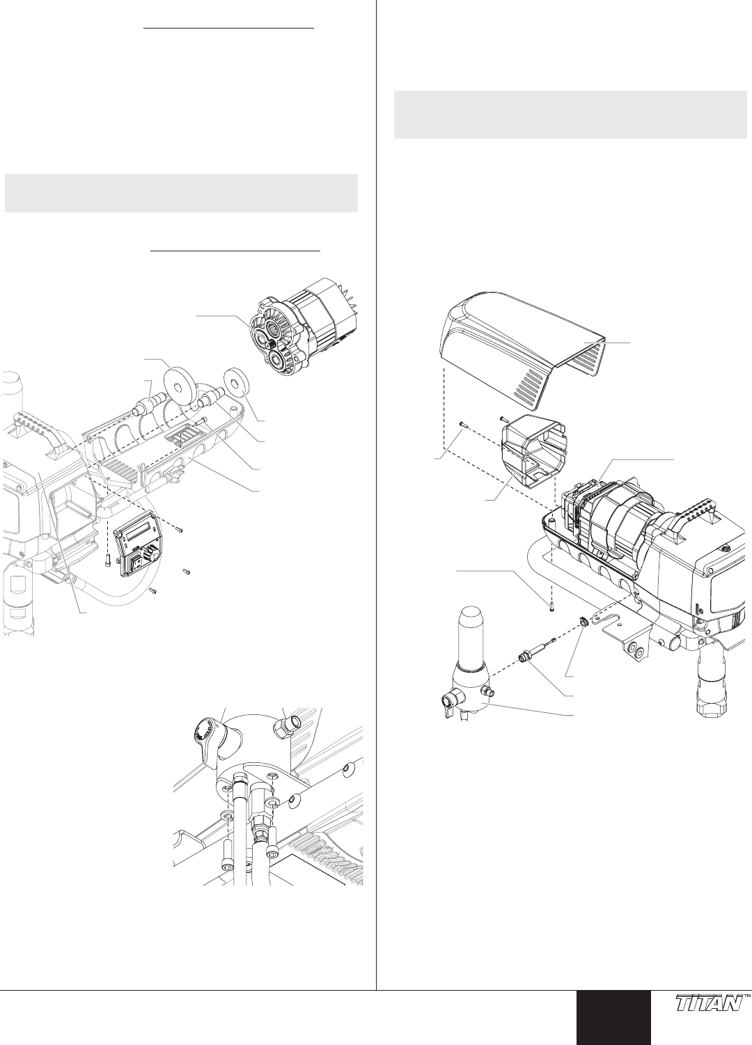
Replacing the Gears
1. Follow steps 1-11 in Replacing the Motor Assembly (page
10) to remove the motor and control panel.
2. Inspect the armature gear on the end of the motor for damage
or excessive wear. If the gear is completely worn out, replace
the motor assembly.
3. Remove and inspect the 1st stage gear and 2nd stage
gear assemblies for damage or excessive wear. Replace, if
necessary.
4. Inspect the front gear box assembly for damage or excessive
wear. If damaged or worn, replace the front gear box
assembly.
NOTE: Clean and rell the gear box cavity up to the rear
face of each gear with Lubriplate (P/N 314-171).
5. Reinstall the motor into the gearbox housing.
6. Follow steps 13-24 in Replacing the Motor Assembly (page
10) to replace the motor and control panel.
Armature Gear
2nd Stage Gear
3rd Stage Pinion
1st Stage Gear
2nd Stage Pinion
Belly Pan
Belly Pan Screw
Front Gear Box Assembly
Replacing the Transducer
1. Unplug the unit.
2. Loosen and remove the
two (2) lter assembly
bolts. Slide the lter
assembly from the cart.
3. Loosen and remove the
two (2) motor shroud
screws. Remove the
motor shroud.
4. Loosen and remove
the two (2) motor cover
screws. Remove the
motor cover.
5. Disconnect the
transducer wire from the
motor controller.
6. Pull the grommet out of the mounting plate and slide it up the
shaft of the transducer until it is clear of the mounting plate.
7. Using a wrench, loosen and remove the transducer from
the lter housing. Carefully thread the transducer wire out
through the mounting plate.
8. Slide the grommet o of the old transducer and onto the new
transducer.
9. Thread the new transducer wire through the mounting plate
and back to the motor controller.
10. Thread the new transducer into the lter housing and tighten
securely with a wrench.
NOTE: Make sure the o-ring on the transducer is in place
before threading the transducer into the lter
housing.
11. Push the grommet into the mounting plate.
12. Connect the transducer wire to the motor controller (refer
to the electrical schematic in the Parts List section of this
manual).
13. Place the motor cover back over the motor controller. Secure
with the two (2) motor cover screws.
14. Slide the motor shroud over the motor assembly.
15. Secure the motor shroud with the two (2) motor shroud
screws.
Motor
Shroud
Screw
Motor
Cover
Motor
Cover
Screw
Motor Shroud
Motor
Controller
Tranducer
Filter assembly
Grommit


