


GX1050 Technical Manual
Page 12
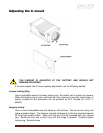
EXTERNAL POWER
This connection provides the main power for the camera. The camera operates from a
DC voltage between 5V to 24V. The current capacity of the power supply can be
estimated by dividing the camera’s power requirement by the external power voltage. It
is also recommended to factor this by about 50% as follows:
Power supply current capacity = (power specification / external voltage) x 1.5
The conductor used for this connection must be adequate for the current consumption
of the camera. For best performance the connection for EXTERNAL POWER should be
physically close to the POWER GROUND connection.
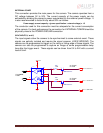
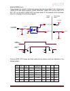
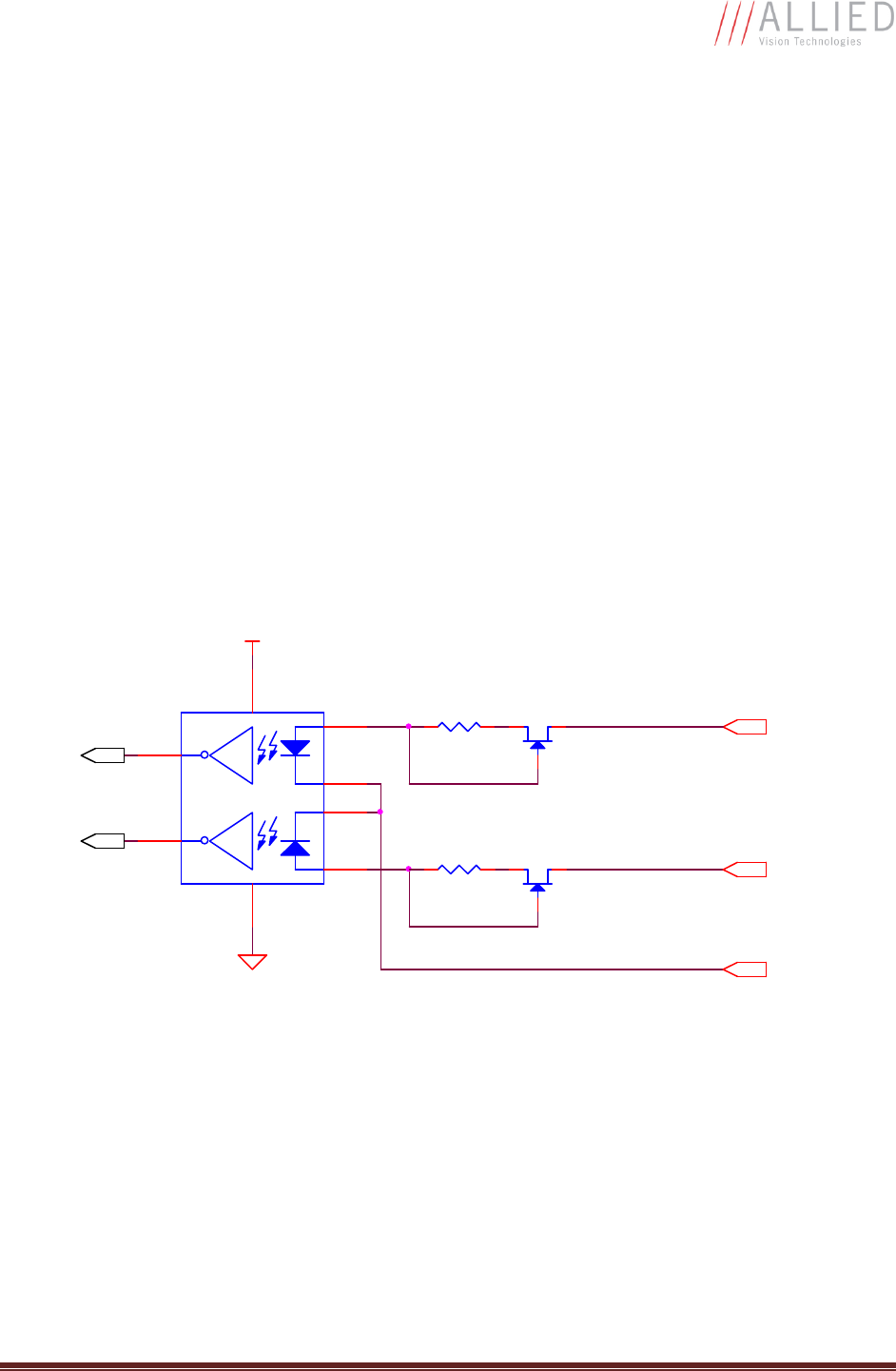
SYNC INPUTS (1 and 2)
The input signals allow the camera to be synchronized to some external event. These
signals are optically isolated and require the signal common (USER GROUND). The
camera can be programmed to trigger on the rising or falling edge of these signals. The
camera can also be programmed to capture an image at some programmable delay
time after the trigger event. These signals can be driven from 5V to 24V with a current
load of 5mA.
VDD+3.3
180R
1/10W
5V TO 24V
IF = 5mA
5V TO 24V
IF = 5mA
PIN 4. SYNC IN 1
180R
1/10W
TO CAMERA
LOGIC
PIN 11. SYNC IN 2
PIN 7. USER GND
DS
G
MMBF4393LT1G
DS
G
MMBF4393LT1G
VCC
GND
HCPL-063L
1
2
3
4
7
6
85