


GX1050 Technical Manual
Page 13
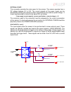
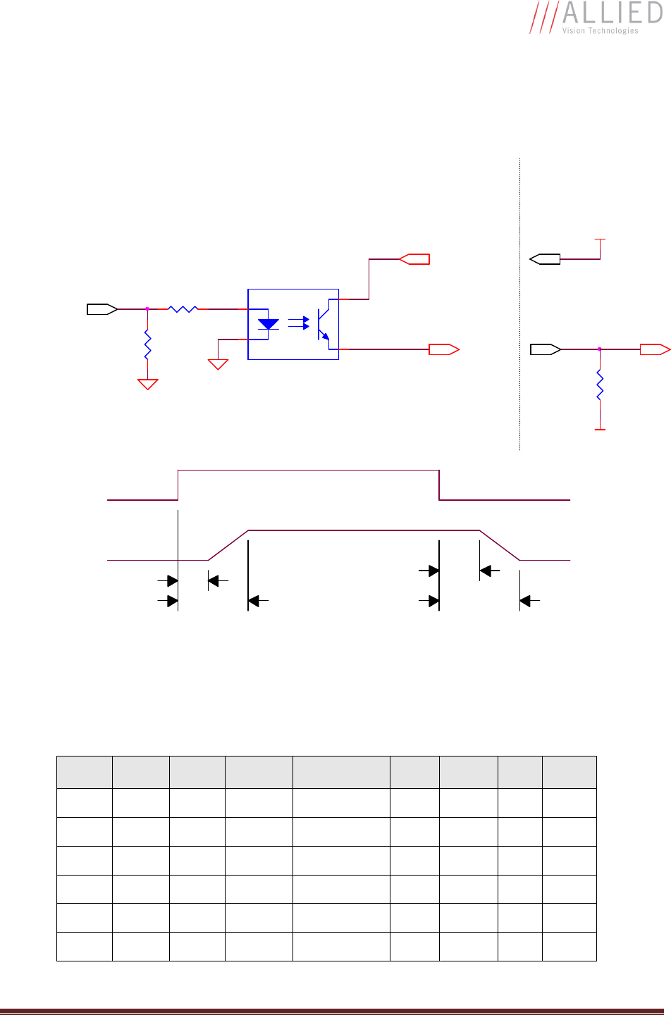
SYNC OUTPUTS (1 to 4)
These signals are optically isolated and require the user to provide a high voltage level
(USER VCC) and signal common (USER GROUND). USER VCC can be from 5V to
24V. ICC is a function of USER VCC and load resistor R. An example of the functional
circuit is indicated in the following diagram.
5V TO 24V
100K
V LOAD
442R
PIN 10. USER VCC
R
VCC-USER
GND-USER
SYNC OUT
USER TRIGGER
CIRCUIT
T4
CAMERA
CIRCUIT
T2
TLP281-4GB
1
2
16
15
T3
IF = 5mA
CAMERA
LOGIC SIGNAL
3.3V CAMERA
LOGIC SIGNAL
SYNC OUT
SIGNAL
T1
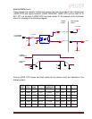
Various USER VCC values and load values for the above circuit are indicated in the
following table:
USER
VCC
USER
ICC
R
LOAD
V LOAD
R POWER
DISSIPATION
T1 T2 T3 T4
5V 8mA 500Ω 4.1V 32mW
1.5
µs
6.5µs 2µs 14µs
5V
4.8mA
1KΩ 4.8V 23mW
1.5
µs
5µs
17
µs
40µs
12V
9.2mA
1.2K
Ω
11.2V 101mW
1.5
µs
11.2
µs
2µs 20µs
12V
4.9mA
2.4K
Ω
11.8V 58mW
1.5
µs
8.5µs
17
µs
55µs
24V
9.5mA
2.4K
Ω
23.2V 217mW
1.5
µs
22µs 2µs 37µs
24V 5mA
4.8K
Ω
23.8V 120mW
1.
5µs
12µs
17
µs
105
µs