


15
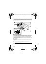
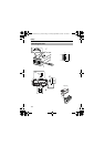
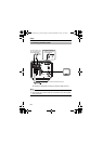
K [AC24V,DC12V] Power input terminal
To connect to AC 24 V or DC 12 V power supply.
(A Pg. 21)
L [AUX,GND] External terminals
This terminal is for the input/output signals that are set in the AUX MODE of
the AUX FUNCTION screen. (A Pg. 36)
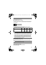
● This terminal also outputs the B&W/Color signal. [Open-collector L signal.
Maximum voltage 25 V, current 30 mA]
● When switching B&W/Color using the control signal, the signals are input
through this terminal. [B&W: MAKE, Color: BREAK]
M [VIDEO OUT] Video signal output connector
This connector outputs a composite video signal. Connect this to the video
input connector of a video monitor, switcher and the like.
N [SELECTOR/SET] Selector switch/Set button
This allows user to select menu screens and change or confirm settings.
(A Pg. 32)
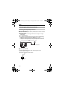
Press the SELECTOR switch up (J) and hold for 1 second to set to
[FOCUS ADJUST MODE] and open the lens iris for easy focusing.
(As the depth of object field is lower, focus can be adjusted accurately.)
(A Pg. 26)
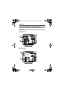
O [MENU] Menu button
When pressed, a menu screen is brought up. (A Pg. 32)
P [INT,LL] Selector Switch for Synchronizing System
This switch sets the synchronizing system for the camera.
INT : This is set for internal synchronization (INT).
LL (Line Lock) : This is set to synchronize the camera’s vertical
synchronization to the power frequency.
(Default setting: INT)
ADCTDN2412N_P_EN.book Page 15 Friday, September 28, 2007 12:49 PM