


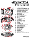
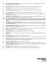
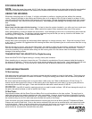

CONTROLS IN DETAIL
1. SHUTTER RELEASE LEVER : Pulling the shutter release lever back part way activates the camera meter and autofocus.
Pulling the lever back all the way fires the camera.
2. SUB-COMMAND INPUT / APERTURE KNOB : Rotates clockwise and counterclockwise. Use alone or in combination with
other controls to select or set various camera functions or modes. In “Manual” the exposure mode controls the aperture
settings (see camera manual).
3. ON / OFF / ILLUMINATOR KNOB : Rotate to switch camera on or off or to engage illuminator.
4. EXPOSURE MODE SELECTOR / FORMAT BUTTON : Press to access the exposure mode (P,S,A,M), rotate Main
Command Knob to select proper exposure mode. This button when pressed at the same time as the delete button (32) will
format the card inside the camera.
5. EXPOSURE COMPENSATION / RESET BUTTON : press to engage the Exposure compensation control [+/-].
Rotate the Main-Command knob to set the desired exposure compensation value.The value will appear in the Top LCD
panel and in the Viewfinder. This button when pressed at the same time as the Quality Selector button (25) will reset the
camera settings to it’s default position.
NEW. EXPOSURE MODE & COMPENSATION CONTROL KNOB: Lift knob and position over setting to be
modified, see description of 4, and 5 for more info on individual setting mode. when done lift knob
and position in neutral position.
6. FLASH SYNC MODE / EXPOSURECONTROL BUTTON:
Turn to activate the flash mode selector function, rotate main
command knob to desired flash sync mode. Exposure compensation is not accessible on non
TTL strobes.
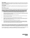
7. BULKHEAD CONNECTOR : For Flash Sync Cord. (Nikonos Type 5 pins).
8. EXTRA BULKHEAD CONNECTOR (OPTIONAL) : For additional Flash Sync Cord. (Nikonos Type 5 pins).
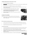
9. FOCUS/ZOOM KNOB : Turning allows manual focus of a single focus lens or rotation of the zoom mechanism of a lens.
9a. FOCUS/ZOOM PINION GEAR : Engages and operates the focus or zoom gear attached to the lens.
10. LENS RELEASE LEVER : activates the lens release button on the camera allowing easy removal of the lens.
11. FOCUS MODE SELECTOR LEVER : Rotate to select between manual, single or continuous focusing.
11a. FOCUS MODE SELECTOR LEVER FORK : Must be in M (manual) position when sliding camera in the
housing, once installed, desired focus mode can be selected.
12. MOUNTING TRAY: This sliding tray is removableto allow easy access and mounting of the camera.
13. HOT SHOE CONNECTOR : connects the camera to the Flash Bulkhead. Slide this Connector into the camera Hot Shoe.
When detaching do not pull the cord as this might damage the electrical connections.
14. HAND GRIPS (X2) : Left and right grip allowing the mounting of strobe arms and accessories.
15. MOUNTING HOLE : These are 1/4-20 TPI holes that are ready to accept TLC Base Brackets or TLC Base Ball for strobe
arms or accessories.
16. BAYONNET MOUNTING FLANGE : allows the mounting of differents ports and extension rings on the housing.
17. AF / AE LOCK LEVER : Press down lever to engage autofocus or/and auto exposure, see camera manual for the different
options associated to this button .
18. TOP LCD WINDOW : displays essential camera operating data.
19. MAIN-COMMAND INPUT KNOB : It rotates clockwise and counterclockwise. It can be used alone or in combination with
other controls to select or set various camera functions or modes. Refer to camera manual for in depth use.
Page 3 of 14