7 - 26
For ease of access to bottom of unit during service
procedures, your unit may be driven up on ramps or
tipped up onto bagger attachment service bar and
braced securely. (For units without a bagger
attachment, a service bar package is available through
your Ariens Dealer.)
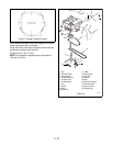
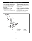
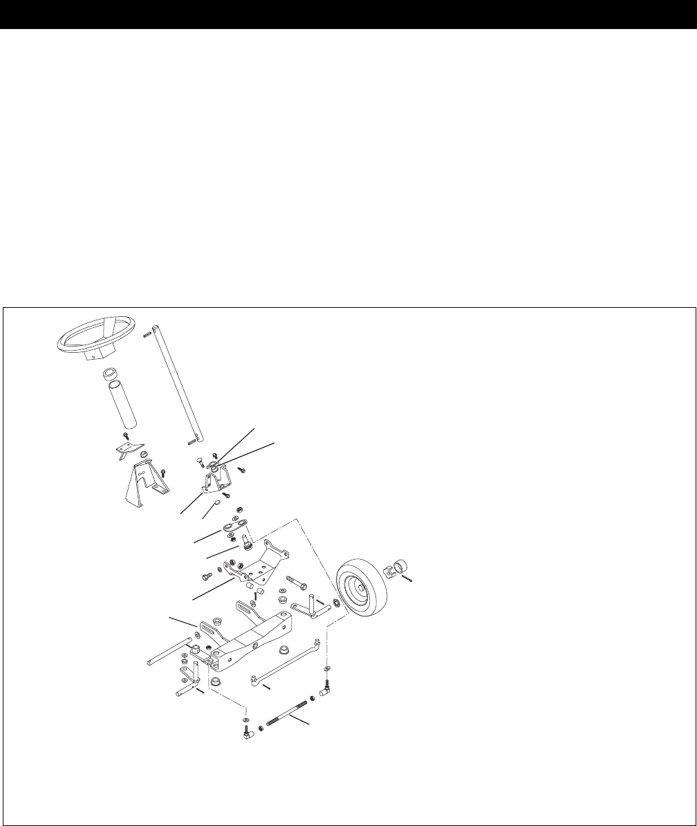
7.1 STEERING SHAFT GEARS
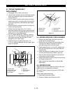
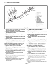
To remove steering shaft with gears:
1. Remove roll pin securing steering wheel to shaft
and remove steering wheel and tube.
2. Remove cotter pin from front link on mower pan
and disconnect link. Refer to Mower Pan section
for removal of mower pan.
3. Remove cotter pin from drag link at tie rod arm and
disconnect drag link.
4. Remove four bolts that secure axle bracket to
frame and remove axle from frame.
5. Remove four taptites securing steering bracket to
mower adjustment bracket. Remove entire steering
assembly out of unit.
6. Check front axle parts for wear and replace as
necessary. Grease before assembly.
7. Assemble in reverse order.
SECTION 7 - STEERING AND CONTROLS
Figure 25
1. Retaining Plate
2. Flange Bushing
3. Steering Bracket
4. Steering Gear
5. Pinion
6. Spacer
7. Drag Link
8. Axle Bracket
9. Axle Assembly
1
2
3
4
5
6
7
8
9
PA0140


