


8 - 28
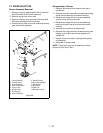
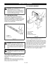
8.1 BRAKE DISASSEMBLY
1. Remove cotter pin securing brake rod to brake
lever
2. Remove nuts and washers securing brake band to
brake lever.
3. Remove cotter pin from pin securing brake lever to
brake bracket.
4. Remove lock nut and lock washer securing friction
wheel hub to pinion shaft and remove brake
assembly.
5. Check all parts for wear and replace as necessary.
6. Assemble in reverse order.
NOTE:
When resetting brake adjustment be sure brake
band does not twist.
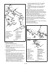
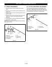
8.2 CLUTCH AND BRAKE ADJUSTMENT
Clutch and brake adjustments are dependent upon
each other. If depressing clutch and brake pedal fully
does not stop riding mower and/or hold it on hill, brake
must be adjusted. See section on Adjustments.
SECTION 8 - BRAKE AND CLUTCH
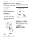
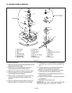
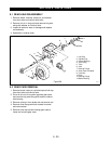
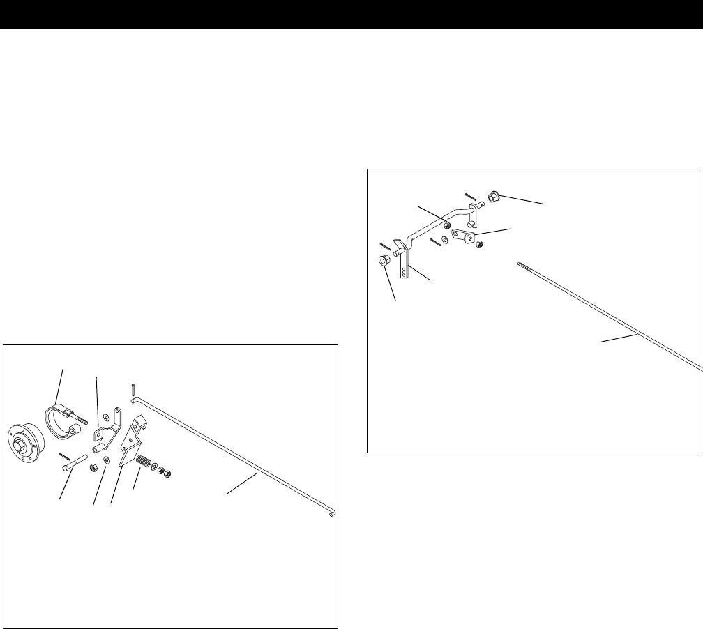
Figure 27
1. Brake Rod
2. Compression Spring
3. Brake Bracket
4. Lock Washer
5. Pin
6. Brake Band
7. Brake Lever
1
2
3
4
5
6
7
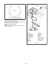
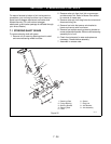
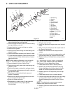
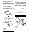
Figure 28
1. Clutch Rod
2. Flange Bushing
3. Lock Nut
4. Clutch Shaft
5. Clutch Bracket
1
2
3
4
5
2