


9 - 30
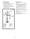
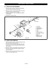
9.1 GEAR CASE DISASSEMBLY
1. Remove locknut from friction disc hub and remove
hub and woodruff key in pinion shaft.
2. Remove flange whizlock screws in cover and using
slots provided pry cover off.
3. Inspect breather in cover and clean or replace.
4. Remove cover gasket.
5. Remove pinion shaft bearing and axle bearing and
inspect for wear.
6. Remove differential assembly and inspect for wear.
7. To test differential assembly insert both axle shafts
and turn one shaft. Other shaft should turn freely in
opposite direction.
NOTE:
When replacing differential, inner spline with
small I.D., should face down inside of gear case.
8. Remove washer from top of pinion shaft.
9. Remove pinion shaft, gear cluster and bearing and
inspect for wear.
10.Remove flat washer under pinion and gear cluster.
11.To remove idler shaft place end of shaft in vise and
tap case with mallet.
12.Check seal and sleeve bushing for wear and
replace if necessary.
13.Remove nuts securing brake bracket to case and
remove bracket. Check for wear.
14.Press out ribbed-neck bolts.
15.Reassemble in reverse order, fill gear case with
8 ounces of Ariens multi-purpose grease,
P/N 00015000.
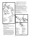
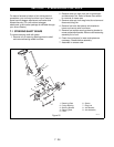
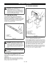
9.3 GEAR CASE REPLACEMENT
1. Bolt gear case to frame.
2. Insert axle guide tool into gear case from inside of
frame.
3. Slide in long axle and secure with washer and roll
pin. Remove axle guide.
4. Replace seal and secure with flange whizlock
screws.
5. Insert short axle and rotate to engage springs and
secure with spindle cup, cotter pin and hub cap.
6. Replace brake rod in brake lever and secure with
cotter pin.
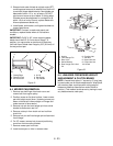
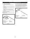
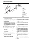
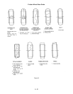
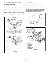
9.4 FRICTION WHEEL REPLACEMENT
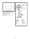
See Figure 31-Friction Wheel Wear Guide.
1. Place speed control lever in neutral position.
2. Remove cap screws and lockwasher securing
friction wheel guard and friction wheel to friction
wheel hub. Remove guard and friction wheel.
3. Replace guard on hub temporarily with two cap
screws.
4. Place speed control lever in forward position.
5. Loosen clutch shaft stop and with clutch arm riding
on stop, position stop in slot to give smallest
distance between guard and drive disc. Secure
stop.
NOTE:
This adjustment ensures proper pressure
between drive plate and friction wheel.
6. Remove guard and install new friction wheel and
guard.
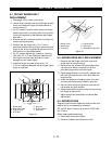
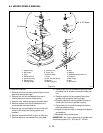
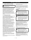
Figure 30
1. Ball Bearing
2. Breather
3. Cover
4. Needle Bearing
5. Pinion & Gear
6. Spacer
7. Idler Shaft
8. Ball Bearing
9. Pinion Shaft
10.Sleeve Bushing
11.Differential Assembly
12.Guard
13.Friction Wheel
14.Friction Wheel Hub
15.Lock Nut
16.Seal
PA0170
1
2
3
4
5
6
7
8
9
10
11
12
13
14
15
16
4
8