


4. To increase protection of cable, place all excess wire and extension
cable in convoluted tubing.
5. Do not twist camera cable, do not cut pigtail, or cable.
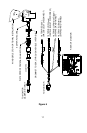
WIRING CAMERA AND MONITOR
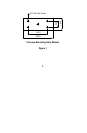
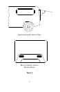
1. See wiring diagram for connections to ignition, ground, and backup
circuit. (See Figure 6)
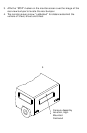
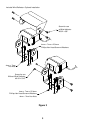
2. Wiring camera:
Drill a 19mm /3/4” diameter hole into the vehicle body near the
camera and bracket.
Connect camera connector to extension cable in vehicle.
Push extra cable into vehicle, (be careful not to kink cable) and fit
grommet into the hole.
Apply sealant around grommet to increase resistance to water
penetration.
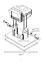
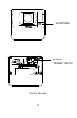
3. Wiring monitor:
Insert extension cable into the camera #1 position if (2) cameras
are used, be sure to mark each extension cable properly and plug
second camera into cable #2 position.
Bundle excess cable together using a cable tie or vinyl tape. This
will avoid possible damage to cable during operation.
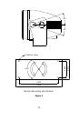
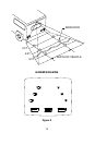
4. The red wire marked ACC is connected to an ignition power source,
the black wire marked GND is connected to chassis ground, and the
blue wire marked BACK is connected to the vehicle’s back up circuit.
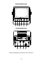
FUNCTIONS AND OPERATION
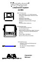
Monitor: See page 12.
1. Power Switch: STD. BY- Monitor operates when vehicle transmission is
switched into “reverse”.
On- Monitor and system operate when ignition switch is
“ON”
2. Input Switch: “A” used mainly for rear mounted camera or as
specified
by the installer.
“B” used mainly for side mounted camera or as
specified
by the installer.
3. Day/Night Switch: Pre-set brightness and contrast levels optimized for
day
and night operation.
4. Contrast: Variable control or contrast. Should be adjusted if the
3