


“Day/Night” switch does not achieve the most
desirable
picture.
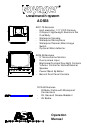
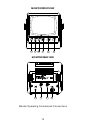
5. Brightness: Variable control of brightness. Should be adjusted if
the
“Day/Night” switch does not achieve the most
desirable
picture.
6. Volume: Variable control of internal speaker and external
speaker
volume.
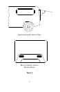
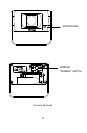
REAR OF MONITOR: See page 12.
1. Power Connection: PIN 1 not used
PIN 2 Ground- Black wire
PIN 3 Reverse circuit- Blue wire
PIN 4 not used
PIN 5 battery back-up- Yellow wire
PIN 6 +12VDC ignition- Red wire
2. Camera A input: Connection to camera extension cable
3. Camera B input: Connection to additional camera
extension
cable
4. External speaker connection: Center pin is positive audio output, used
to
disable the internal speaker and remotely
mount a speaker for driver convenience.
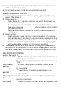
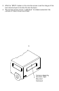
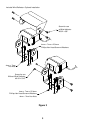
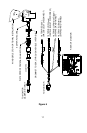
CAMERA CONTROLS AND COMPONENTS
Camera: See page 13
1. Microphone- Waterproof microphone for audio pick up
2. Mirror/Normal Switch- Waterproof switch, to change camera image
from a mirror view (rear of vehicle mounted), to normal view (side or
front mounted camera). See Figure 7.
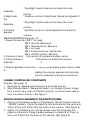
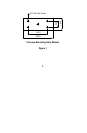
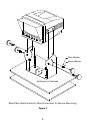
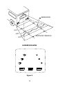
AFFIXING DISTANCE MARKERS TO THE MONITOR SCREEN
1. Clean monitor screen surface of fingerprints. Set the camera into the
“DOWN” position. Place the distance indicators behind the vehicle at
3 feet, 6 feet, and 9 feet from the back of the vehicle. (See Figure 8)
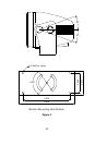
2. Attach the markers to the monitor screen over the images of the
distance indicators. These markers represent a distance of 3 feet, 6
feet, and 9 feet from the back of the vehicle. (See Figure 8)
4