


2
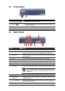
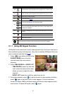
1.3 Front Panel
(1)(2)(3) (4)
Name Function
(1) DVR Power LED
: Light when the unit is power on
(2) HDD LED
: Indicate the hard disk running state. Light when the HDD is
running (Read/Write)
(3) IR Sensor
:
Receive signal from the remote control to operate the unit
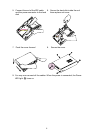
(4) USB 2.0 Port
:
Connect to pen drive / external hard disk for backup
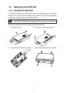
1.4 Back Panel
(1) (2) (4) (6) (8) (9) (11)(12)
(3) (5) (7) (10)
Name Function
(1) RJ-45 port : Ethernet connection port
(2) Audio In : Input the audio signal from audio output device which it has a
power supply by itself. The audio is embedded with channel 1
(3) Audio Out : Output the audio signal to a audio out device which it has a power
supply by itself
(4) CH1 : Input the video camera signal and display it on channel 1
(5) CH2 : Input the video camera signal and display it on channel 2
(6) CH3 : Input the video camera signal and display it on channel 3
(7) CH4 : Input the video camera signal and display it on channel 4
Output the video signal to other vedio output device through BNC
port
(8) Video Out :
The DVR unit support 2 video output ports and you can
only select to output the video either from the VGA OUT or
VIDEO OUT
(9) VGA OUT : Output the video signal to a CRT or LCD monitor
(10) Sensor In &
Alarm Out
: Support up to 4 sensor device and 1 relay device (Relay: 1A @
125V AC/30V DC)
(11) TV-VGA Switch : Switch to select the video output. Make sure to set the video output
before turning on the unit
(12) 12V DC : Connect the power adapter into this port