


50
AXIS 231D+/232D+ - Connection Module
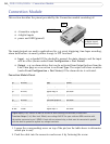
Connection Module
This section describes the pinout provided by the Connection module consisting of:
24V AC Power
used
4 transistor outputs
(see table below)
4 digital inputs
not
• 4 transistor outputs
• 4 digital inputs
• power and GND (ground)
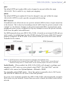
The inputs/outputs are used in applications for, e.g. event triggering, time lapse recording,
alarm notification via email, picture storage to FTP locations.
• Input - e.g. a doorbell. If the doorbell is pressed, the state changes, and the input
will be active (shown under Event Configuration > Port Status).
• Output - e.g. an alarm device that can be activated from Output buttons from the
Live View page or as an action to an Event Type. The output will show as active
(under Event Configuration > Port Status), if the alarm device is activated.
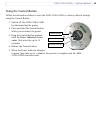
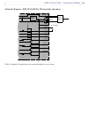
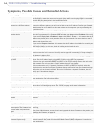
Connection Module Pinout
1. Loosen the corresponding screw on top of the pin (see the table above to determine
which pin to use).
2. Push the cable into the connector and secure it by fastening the screw.
Function Description Function Description
n/a not used GND ground
n/a not used
GND ground
n/a not used Transistor Output 4 See below
n/a not used
Digital Input 4 See below
n/a not used Transistor Output 3 See below
n/a not used
Digital Input 3 See below
n/a not used Transistor Output 2 See below
PS GND ground
Transistor Output 1 See below
24 VAC 24 VAC Digital Input 2 See below
24 VAC 24 VAC
Digital Input 1 See below
Digital Input (1-4)- connect to GND to activate or leave floating (unconnected) to deactivate
Transistor Output (1-4)- Max. load 100mA, max. voltage 24V DC. An open-collector NPN transistor with
the emitter connected to pin 2 (GND). If used with an external relay, a diode must be connected in parallel
with the load for protection against any voltage transients.