


7
AXIS 231D+/232D+ - Description
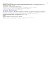
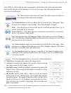
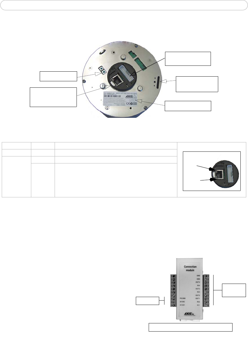
Hardware Description
Serial number
Connection module
connector
Network connector
S/N
with Network and
Power Indicators
Control button
Mounting slot for
fixing screw
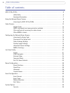
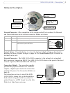
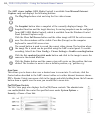
Network Connector- After completion of the startup and self test routines, the Network
and Power Indicators on the network connector flashes as follows:
Indicator Color Description
Detail - network connector:
Network
Indicator
Power
Indicator
Network Green Flashes for network activity
Power Green Normal operation
Amber Flashes green/amber during upgrade and when connecting to
AXIS Internet Dynamic DNS Service
Control Button - Press this button to restore the factory default settings, as described in
Resetting to Factory Default Settings, on page 48. The Serial Number (S/N) is located on
the label on the unit.
Network Connector - The AXIS 231D+/232D+ connects to the network via a standard
RJ45 connector. Supporting NWAY, the AXIS 231D+/232D+ detects the speed of the local
network segment (10BaseT/100BaseTX Ethernet).
Connection Module - The connection module
provides the physical interface to 4 transistor
outputs, 4 digital inputs and is the connection
point for AC power. See
Connection Module, on
page 50
AC Power
4 outputs
4 inputs
Connection module connector
.
For instructions on how to install the AXIS
231D+/232D+, please refer to the Installation
Guide which is supplied with the product in
printed format or in PDF format from the Axis
Web site at http://www.axis.com