


2
290A Installation Instructions
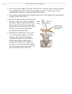
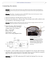
4. Attach the camera to the camera mounting board (7) using the screw attached to the
board. You will find a screw hole at the bottom of the camera. Before tightening the
screw, position the camera with the board inside the housing (with the lens to the
front) and determine the camera’s correct position.
Caution: The lens should be as close to the window as possible allowing sufficient space between the lens
and window to accommodate the zoom function (if supported by the lens).
5. Once the correct position has been established, lift out the camera with the board
while keeping it in the correct position. Tighten the screw at the bottom to securely
affix the camera to the board.
Caution: The heater at the front of the housing unit becomes hot when in operation. If applicable, position
the cable connected from the DC IRIS socket to the lens so that it does not touch the heater.
Caution: Do not over-tighten the screw as you may damage the camera.
6. Position the camera with the board inside the housing as before. Make sure the board
is inserted under the lugs beneath the window in its most forward position. Use the
two screws (6) to secure the board with the camera and lens in the housing.
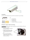
Routing the cables
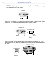
1. Route the cables (network and mains power) to the location where the bracket arm is
to be installed.
Note:
The cables can either be routed through the bracket arm (recommended) or through a hole in the base of
the bracket. This hole needs to be drilled in the recess area where the casing metal is thinner to accommo-
date easy drilling.
Determine the size of the hole to accommodate the fitment of the cable gland (not supplied). However, the
hole should not exceed 15mm in diameter.
Warning: Install cable glands and/or cables that are suitable for external use that and are in compliance
with local laws and regulations.