


AXIS A1001 Installation Guide Page 15
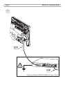
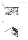
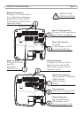
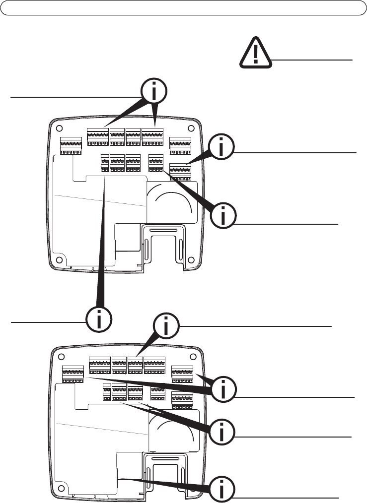
Power connector
DC input: 10–30VDC,
max 26W
Max load on
outputs: 14 W
AWG 28–16 (CSA)
AWG 30–14 (CUL/UL)
Door connectors
Digital input: 0 to max 40VDC
Reader data connectors
Max cable length: 30 m (98.4 ft)
RS485 full duplex
RS485 half duplex
Wiegand
Reader I/O connectors
DC output: 12VDC, max 300mA
2x 4 congurable inputs/outputs:
Digital input: 0 to max 40VDC
Digital output: 0 to max 40VDC,
open drain, 100mA
Power & Relay connector
DC output: 12VDC, max 500mA
Relay: 30VDC, max 700mA
Power lock connector
2x 12 V DC
0 V DC, oating, or 12VDC,
max total load: 500 mA
Auxiliary connector
DC output: 3.3VDC, max 100mA
Digital input: 0 to max 40VDC;
Digital output: 0 to max 40VDC,
open drain, 100mA
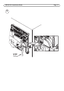
READER I/0 1 &2
RELAY & PWR
LOCK
DC IN
AUX
READER DATA 1 & 2
DOOR IN 1 &2
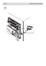
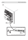
Network Connector
RJ45, PoE IEEE 802.3af/
802.3at Type 1 Class 3
Max load on outputs: 7.5 W