


AXIS M1145 Network Camera
Technical Specifications
Function/group
Item
Specications
Optional
accessories
AXIS T91A04 Camera Holder
AXIS T91A05 Camera Holder
AXIS P8221 Audio Module
AXIS T90A White LED Illuminators
AXIS PoE products
Languages
German, French, Spanish, Italian, Russian, Simplied Chinese, Japanese, Korean,
Portuguese
Warranty
Axis 1–year warranty and AXIS Extended Warranty option, see www.axis.com/warranty
Video
management
software (not
included)
AXIS Camera Companion (included), AXIS Camera Station and video management
software from Axis’ Application Development Partners (not included). See
www.axis.com/products/video/software
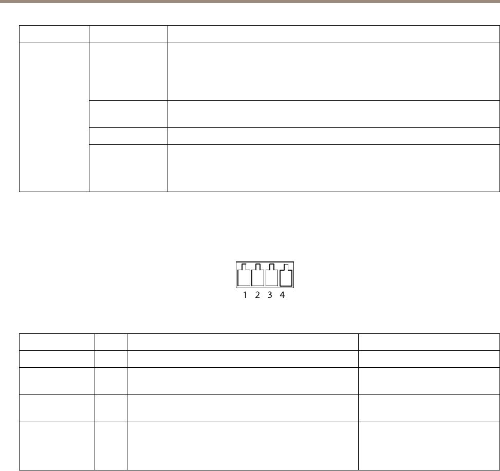
Connectors
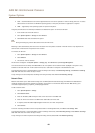
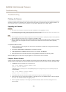
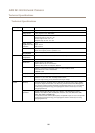
I/O Connector
4-pin terminal block for:
• Auxiliary power (DC output)
• Digital Input
• Digital Output
• 0 V DC (-)
1 2 3 4
Function Pin Notes
Specications
0 V DC (-)
1
0 V DC
DC output
2
Can be used to power auxiliary equipment.
Note: This pin can only be used as power out.
3.3 V DC
Max load = 50 mA
Digital Input
3
Connect to pin 1 to activate, or leave oating (unconnected)
to deactivate
0 to max 40 V DC
Digital Output
4
Connected to pin 1 when activated, oating (unconnected)
when deactivated. If used with an inductive load, e.g. a relay,
a diode must be connected in parallel with the load, for
protection against voltage transients.
0 to max 40 V DC, open drain,
100 mA
58