


AXIS M1145–L Network Camera
Hardware Overview
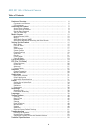
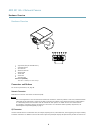
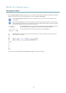
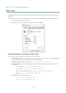
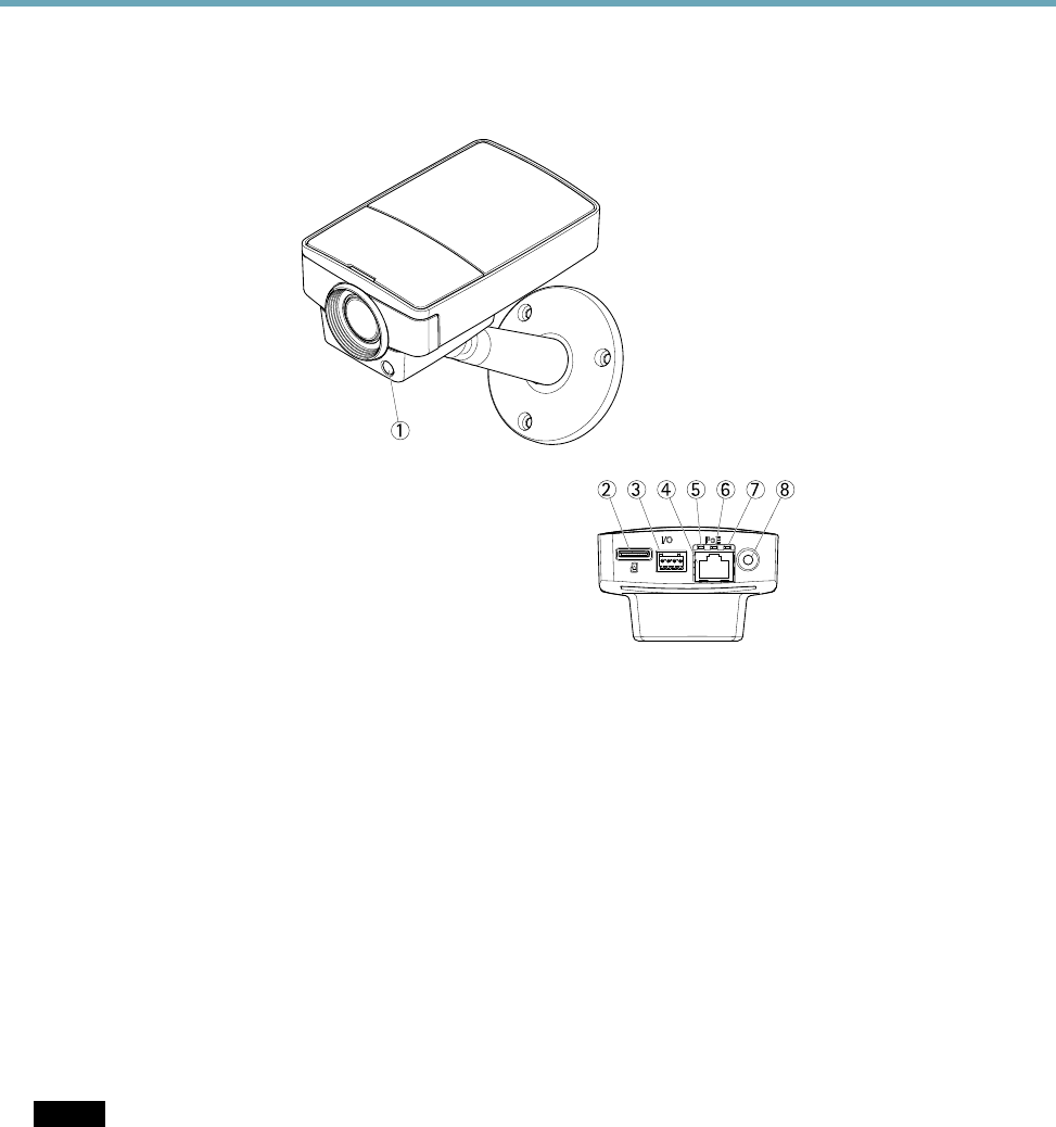
Hardware Overview
1
2 3 4 5 6 7 8
1.
Light sensor (only for AXIS M1145–L)
2.
microSD card slot
3.
I/O connector
4.
Network connector
5.
Network LED
6.
Status LED
7.
Power LED
8.
Control button
Dimensions (HXWXD)
44 x 75 x 114 mm (1.7 x 3.0 x 4.4 in)
Connectors and Buttons
For technical specications, see page 56.
Network Connector
RJ45 Ethernet connector with Power over Ethernet (PoE).
NOTICENOTICE
NOTICE
Due to local regulations or the environmental and electrical conditions in which the product is to be used, a shielded network
cable (STP) may be appropriate or required. All cables connecting the product to the network and that are routed outdoors
or in demanding electrical environments shall be intended for their specic use. Make sure that the network devices
are installed in accordance with the manufacturer’s instructions. For information about regulatory requirements, see
Electromagnetic Compatibility (EMC), on page 2 .
I/O Connector
Use with external devices in combination with, for example, tampering alarms, motion detection, event triggering, time lapse recording
and alarm notications. In addition to the 0 V DC reference point and power (DC output), the I/O connector provides the interface to:
6