


AXIS M1145–L Network Camera
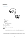
Hardware Overview
• Digital output – For connecting external devices such as relays and LEDs. Connected devices can be activated by the
VAPIX® Application Programming Interface, output buttons on the Live View page or by an Action Rule. The output will
show as active (shown under System Options > Ports & Devices) if the alarm device is activated.
• Digital input – An alarm input for connecting devices that can toggle between an open and closed circuit, for example:
PIRs, door/window contacts, glass break detectors, etc. When a signal is received the state changes and the input becomes
active (shown under System Options > Ports & Devices).
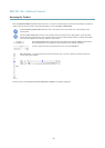
SD Card Slot
A microSD card (not included) can be used for local recording with removable storage. For more information, see Technical
Specications, on page 56.
NOTICENOTICE
NOTICE
To prevent corruption of recordings, the SD card should be unmounted before removal. To unmount, go to Setup > System
Options > Storage > SD Card and click Unmount.
Control Button
The control button is used for:
• Resetting the product to factory default settings. See page 51.
• Connecting to an AXIS Video Hosting System service. See page 44. To connect, press and hold the button for about 1
second until the Status LED ashes green.
• Connecting to AXIS Internet Dynamic DNS Service. See page 44. To connect, press and hold the button for about 3 seconds.
LED Indicators
LED
Color
Indication
Green
Steady for connection to a 1 Gbit/s network. Flashes for network activity.
Amber
Steady for connection to a 10/100 Mbit/s network. Flashes for network activity.
Network
Unlit No network connection.
Green Steady green for normal operation.
Amber
Steady during startup and when restoring settings.
Status
Red
Slow ash for failed upgrade.
Green
Normal operation.Power
Amber
Flashes green/amber during rmware upgrade.
Note
• The Status LED can be congured to be unlit during normal operation. To congure, go to Setup > System Options > Ports
& Devices > LED. See the online help for more information.
• The Status LED can be congured to ash while an event is active.
• The Status LED can be congured to ash for identifying the unit. Go to Setup > System Options > Maintenance .
• The Power LED can be congured to be unlit during normal operation. To congure, go to Setup > System Options > Ports
& Devices > LED. See the online help for more information.
• The Network LED can be disabled so that it does not ash when there is network trafc. To congure, go to Setup > System
Options > Ports & Devices > LED. See the online help for more information.
7