


32
AXIS P1311 - System Options
There are four types of traps available for the AXIS P1311.
• Cold start
•Warm start
•Link up
• Authentication failed
SNMP v3
SNMP V3 - provides encryption and secure passwords. HTTPS must
be enabled. To use traps with SNMP v3 an SNMP v3
management application is required.
If the Enable S
NMP v3 option is enabled, provide the Initial user password. Note that the initial password is activated only
when HTTPS is enabled and can only be set once.
If HTTPS is enabled, SNMP v1 and
SNMP v2c should be disabled.
When SNMP configuration is ready, click Save to u
se the new settings or Reset to return to the default values.
UPnP™
The network camera includes support for UPnP™. UPnP™ is enabled by default, and the network camera then is automatically
detected by operating systems and clients that support this protocol.
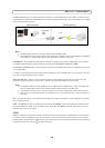
RTP
RTP/ MPEG-4 & H.264 - These settings are the port range, IP address, port number (video and audio), and Time-To-Live
value to use for the video stream(s) in multicast MPEG-4 and H.264 format. Only certain IP addresses and port numbers
should be used for multicast streams. For more information, please see the online help.
Bonjour
The network cameras include support for Bonjour. When enabled, the camera is automatically detected by operating systems
and clients that support this.
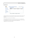
Storage
The Disk Management window is used to set up and manage local storage. It is used to connect memory cards for recording
video, monitoring a disk's status, enabling automatic cleanup, and preventing a memory card's memory from being
overwritten.
Storage Device - is used to identify and monitor the status of the SD card.
It shows the size of the SD card and how free
space is available for storage. It is also used to mount and format SD cards for local storage.
Device Settings - is used to configure removal of recorded video. Automatic disk cleanup
can be enabled and set up
according to a schedule, and an SD card can be locked to prevent storage removal.
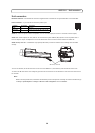
Ports & Devices
I/O Ports - The pinout, interface support and the control and monitoring functions provided by this connector are described
in Unit connectors, on page 36.
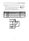
LED
The Status indicator LED on the front of the camera can be set to flash at a configurable interval (or to not light up at all)
when the unit is accessed. For a listing of all LED behavior, see page 5, or the online help. Note that
the LED does not flash
when the stream is retrieved using multicast.