


AXIS P1353–E Network Camera
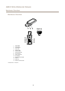
Hardware Overview
1
2
3
4
5
6
7
8
9
10
11
12
13
14
15
16
17
18
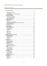
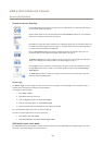
1
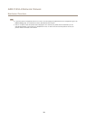
Sunshield adjustment
2
Sunshield
3
Top cover
4
Network camera
5
Safety wire tab
6
Cable hole
7
Network connector
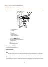
8
Bottom cover screws (4x)
9
Cable cover
10
Cable cover screws (2x)
11
Bottom cover
12
Heaters. Caution!Caution!
Caution!
May be hot.
13
Network cable (route through wall bracket)
14
Bracket adapter
15
Bracket screws (4x)
16
Bracket adjustment screw
17
Wall bracket
18
Alternative cable hole
Connectors and Buttons
For technical specications, see page 66.
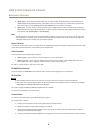
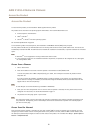
Network Connector
RJ45 Ethernet connector with Power over Ethernet (PoE).
NONO
NO
TICETICE
TICE
The product shall be connected using a shielded network cable (STP). All cables connecting the product to the network shall
be intended for their specic use. Make sure that the network devices are installed in accordance with the manufacturer’s
instructions. For information about regulatory requirements, see Electromagnetic Compatibility (EMC) on page 2 .
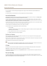
I/O Connector
Use with external devices in combination with, for example, tampering alarms, motion detection, event triggering, time lapse recording
and alarm notications. In addition to the 0 V DC reference point and power (DC output), the I/O connector provides the interface to:
7