


AXIS P1354–E Network Camera
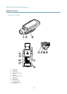
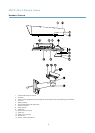
Hardware Overview
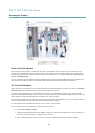
15.
Bracket screws (4x)
16.
Bracket adapter
17.
Network cable (route through wall bracket). Cable not included
18.
Wall bracket
19.
Bracket adjustment screw
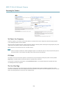
Connectors
For technical specications, see page 60.
Network connector - RJ45 Ethernet connector. Supports Power over Ethernet (PoE).
NOTICENOTICE
NOTICE
The product shall be connected using a shielded network cable (STP). All cables connecting the product to the network switch
shall be shielded (STP) and intended for their specic use. Make sure that the network switch is properly grounded. For
information about regulatory requirements, see Regulatory Information, on page 2 .
Audio in (pink) - 3.5 mm input for a mono microphone, or a line-in mono signal (left channel is used from a stereo signal).
Audio out (green) - 3.5 mm output for audio (line level) that can be connected to a public address (PA) system or an active speaker
with a built-in amplier. A stereo connector must be used for audio out.
SD card slot - A standard or high-capacity microSD card (not included) can be used for local recording with removable storage.
NOTICENOTICE
NOTICE
To prevent corruption of recordings, the SD card should be unmounted before removal. To unmount, go to Setup > System
Options > Storage > SD Card and click Unmount.
Control button - The control button is used for:
• Enabling the Focus Assistant. Press and very quickly release the Control button.
• Resetting the product to factory default settings. See page 54.
• Connecting to an AXIS Video Hosting System service. See page 47. To connect, press and hold the button for
about 1 second until the Status LED ashes green.
• Connecting to AXIS Internet Dynamic DNS Service. See page 48. To connect, press and hold the button for
about 3 seconds.
Power connector - 2-pin terminal block for power input. Use a limited power source (LPS) with either a rated output power
limited to £100 W or a rated output current limited to £5 A.
I/O terminal connector - Use in applications for e.g. motion detection, event triggering, time lapse recording and alarm notications.
In addition to an auxiliary power and a GND pin, the I/O terminal connector provides the interface to:
• Digital output – For connecting external devices such as relays and LEDs. Connected devices can be activated by
the VAPIX® Application Programming Interface, output buttons on the Live View page or by an Action Rule. The
output will show as active (shown under System Options > Ports & Devices) if the alarm device is activated.
• Digital input – An alarm input for connecting devices that can toggle between an open and closed circuit, for
example: PIRs, door/window contacts, glass break detectors, etc. When a signal is received the state changes and
the input becomes active (shown under System Options > Ports & Devices).
Note
The I/O connector is connected to the housing (fan/heater) on delivery, and will trigger an input port event to indicate a fan
or heater error when activated. See Events, on page 39 for information about events.
8