


AXIS P1357–E Network Camera
Technical Specications
Function/group
Item
Specications
Video
management
software (not
included)
AXIS Camera Companion (included)
AXIS Camera Station and video management software from Axis’ Application
Development Partners (sold separately). For more information, see
www.axis.com/products/video/software
Optional
accessories
AXIS T90A Illuminators
AXIS T8414 Installation Display
AXIS T8123 High PoE Midspan 1-Port
Mounting accessories
Lenses
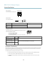
Connectors
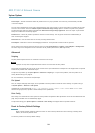
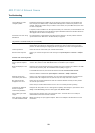
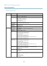
I/O terminal connector
4–pin terminal block for:
• Digital Input
• Digital Output
• Auxiliary power and ground (GND)
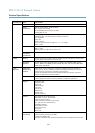
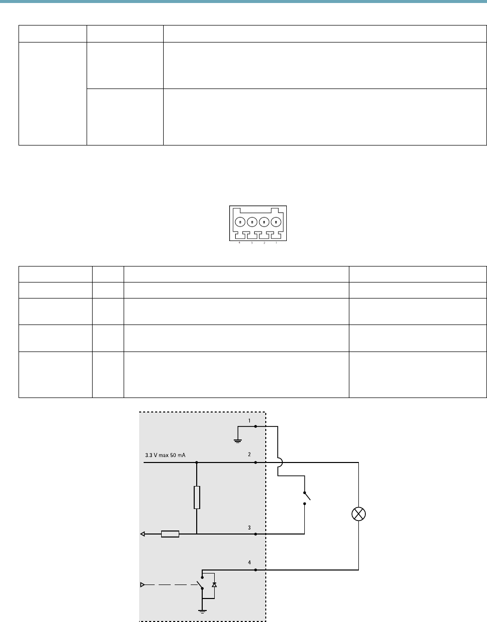
Function Pin Notes
Specications
GND
1
Ground
3.3 V DC Power
2
Can be used to power auxiliary equipment.
Note: This pin can only be used as power out.
Max load = 50 mA
Digital Input
3
Connect to GND to activate, or leave oating (unconnected)
to deactivate.
0 to +40 V DC
Digital Output
4
Internal connection to ground when activated, oating
(unconnected) when deactivated. If used with an inductive
load, e.g. a relay, a diode must be connected in parallel with
the load, for protection against voltage transients.
Max load =100 mA
Max voltage = +40 V DC
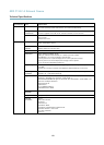
3.3 V max 50 mA
1
2
3
4
63