


Page 10 AXIS Q1602-E/AXIS Q1604-E Installation Guide
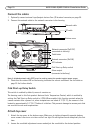
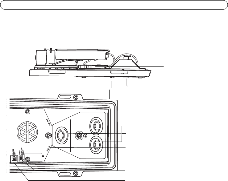
Connect the cables
1. Optionally connect external input/output devices. See
I/O terminal connector,
on page 20.
2. Connect the network cable to the network connector in the housing.
Note: A shielded network cable (STP) must be used to protect the product against power surges.
3. Check that the status LED on the housing indicates the correct conditions. See the table on
page 22 for further details.
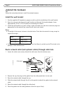
Cold Start-up Delay Switch
This switch is enabled by default; ensure it remains on.
The housing used in this Axis product features Arctic Temperature Control, which is enabled by
setting the Cold Start-up Delay switch to I (ON). When enabled, this function controls when the
camera restarts after a power cut, when temperatures are below 0 °C (32 °F); the camera is first
heated to approximately 0 °C (32 °F) before it initializes. This prevents damage to camera parts that
are sensitive to sub-zero temperatures.
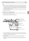
Attach top cover
1. Attach the top cover to the bottom cover. Make sure to tighten diagonally opposite bottom
cover screws a few turns at a time until all are tight. Do not tighten screws completely the first
time.
2. Loosen the sunshield adjustment screws and adjust the sunshield to the desired position.
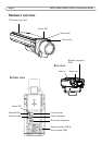
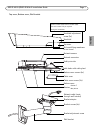
Cable holes
Network connector (PoE IN)
Alarm output
Cold Start-up Delay switch
LED indicator
Network connector (PoE OUT,
connected at delivery)
Bottom cover
I/O cable
Network cable
(connected at delivery)