


AXIS Q1602-E/AXIS Q1604-E Installation Guide Page 21
ENGLISH
Note:
See the User Manual for more information.
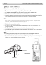
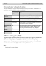
LED indicators on camera
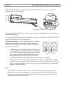
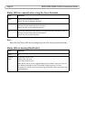
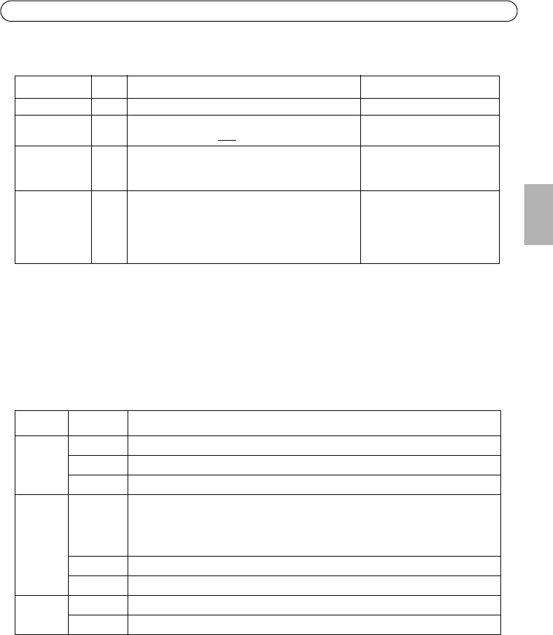
Function Pin Notes Specifications
GND 1 Ground
3.3 V DC
Power
2 Can be used to power auxiliary equipment.
Note: This pin can only
be used as power out.
Max load = 50 mA
Digital
Input
3 Connect to GND to activate, or leave floating
(unconnected) to deactivate.
Note: Connected to housing at delivery.
0 to +40 V DC
Digital
Output
4 Internal connection to ground when activated,
floating (unconnected) when deactivated. If used
with an inductive load, eg. a relay, a diode must
be connected in parallel with the load, for pro-
tection against voltage transients.
Max. load =100 mA
Max. voltage = + 40 V DC
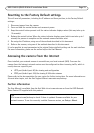
LED Color Indication
Network Green Steady for connection to a 100 Mbit/s network. Flashes for network activity.
Amber Steady for connection to 10 Mbit/s network. Flashes for network activity.
Unlit No network connection.
Status Green Steady green for normal operation.
Note: The Status LED can be configured to be unlit during normal operation, or to
flash only when the camera is accessed. To configure, go to Setup > System
Options > LED settings. See the online help files for more information.
Amber Steady during startup, during reset to factory default or when restoring settings.
Red Slow flash for failed upgrade.
Power Green Normal operation.
Amber Flashes green/amber during firmware upgrade.