


AXIS Q1615-E Network Camera
Hardware Overview
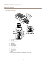
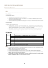
2.
Bottom cover
3.
Bottom cover screws (4x)
4.
Bracket adjustment screw
5.
Wall mount
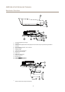
Connectors and Buttons
For technical specications, see page 65.
Network Connector
RJ45 Ethernet connector with Power over Ethernet (PoE).
NONO
NO
TICETICE
TICE
Due to local regulations or the environmental and electrical conditions in which the product is to be used, a shielded network
cable (STP) may be appropriate or required. All cables connecting the product to the network and that are routed outdoors
or in demanding electrical environments shall be intended for their specic use. Make sure that the network devices
are installed in accordance with the manufacturer’s instructions. For information about regulatory requirements, see
Electromagnetic Compatibility (EMC) on page 2 .
I/O Connector
Use with external devices in combination with, for example, tampering alarms, motion detection, event triggering, time lapse recording
and alarm notications. In addition to the 0 V DC reference point and power (DC output), the I/O connector provides the interface to:
• Digital output – For connecting external devices such as relays and LEDs. Connected devices can be activated by the
VAPIX® Application Programming Interface, output buttons on the Live View page or by an Action Rule. The output will
show as active (shown under System Options > Ports & Devices) if the alarm device is activated.
• Digital input – An alarm input for connecting devices that can toggle between an open and closed circuit, for example:
PIRs, door/window contacts, glass break detectors, etc. When a signal is received the state changes and the input becomes
active (shown under System Options > Ports & Devices).
Note
The I/O connector is connected to the housing (fan/heater) on delivery. In the case of a fan or heater error, an input signal
will be triggered in the camera. Set up an action rule in the camera to congure which action the signal shall trigger. For
information about events and action rules, see Events on page 43.
Audio Connector
The Axis product has the following audio connectors:
• Audio in (pink) – 3.5 mm input for a mono microphone, or a line-in mono signal.
• Audio out (green) – 3.5 mm output for audio (line level) that can be connected to a public address (PA) system or an
active speaker with a built-in amplier. A stereo connector must be used for audio out.
RS485/RS422 Connector
Two terminal blocks for RS485/RS422 serial interface used to control auxiliary equipment such as PTZ devices.
SD Card Slot
A microSD card (not included) can be used for local recording with removable storage. For more information, see Technical
Specications on page 65.
NONO
NO
TICETICE
TICE
To prevent corruption of recordings, the SD card should be unmounted before removal. To unmount, go to Setup > System
Options > Storage > SD Card and click Unmount.
8