


Page 12 AXIS Q87-E Installation Guide
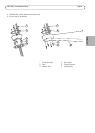
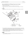
6. If applicable, connect the illuminator cable to the connector (ALARMS and 1) on the base.
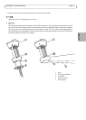
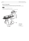
7. Using a RJ45 crimp tool, strip and crimp the network cable according to the manufacturer’s instructions.
8. Connect the network cable to the network connector on the base.
The power supply specified with the product shall be used. Using any other power supply will void the war-
ranty and could leave the unit at a risk.
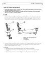
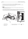
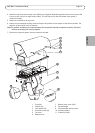
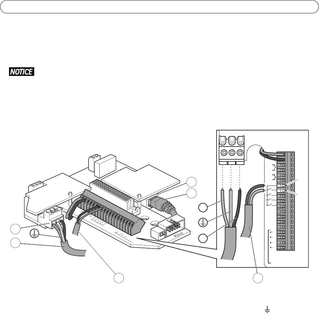
9. 234Connect the 24 V AC power cable to the power connector on the base. Make sure the green/yellow ground
wire is connected to the middle pin. To make the installation easier, it is possible to remove the connector
from the circuit board and mount it when the cables are correctly connected.
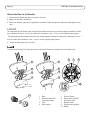
RS495 term. Line
1
2
VIDEO
GND
B+
B-
A B
1
2
A B
485
REL. 2
REL. 1
ALARM
1
2
3
4
VIDEO
GND
B+
B-
A
1
1
234
2
RS485
BAB
REL.2
REL.1
ALARMS
Pos.7
(-)
Pos.8
(+)
4
5
2
3
11
L
N
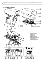
1 Illuminator cable 4
Power cable (24 V AC, blue – L, green/yellow – , brown – N)
2 Network connector 5 Power connector (24 V AC)
3Network cable