


LTC 9384 Series | Instruction Manual | Installation
EN
|
11
Bosch Security Systems | September 1, 2004
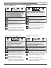
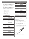
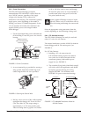
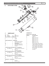
For 24 Volt Cameras:
1. Installing a 24 volt camera into the
LTC 9384/60 Housing uses the internal
transformer for camera power (see FIGURE 7).
2. Connect the supply (115VAC) to the primary
flying leads of the transformer (white wire/pin 1,
black wire/pin 6). Use the wire nuts provided
for this connection.
3. Connect the secondary flying leads (white/black
striped wires/pins 7 and 12) to the camera's
24 volt input. See wiring diagram FIGURE 8
for clarification and FIGURE 5 for power
connection drawings.
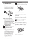
FIGURE 8 LTC 9384/60 Transformer Wired for
24 Volt Camera
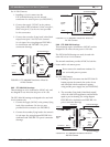
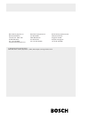
5.6.5 LTC 9384/20 Housings
These housings are to be connected to 24VAC only, and
are designed for use where the site power is 24 volts.
The LTC 9384/20 housings are designed to be used with
24 volt cameras only.
1. Connect the supply (24VAC) to the primary flying
leads of the transformer. Use the wire nuts
provided for this connection (see FIGURE 9).
2. Connect the secondary flying leads to the camera's
24 volt input. See wiring diagram FIGURE 9 for
clarification and FIGURE 5 for power connection
drawings.
FIGURE 9 LTC 9384/20 Transformer Wired for
24 Volt Camera
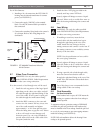
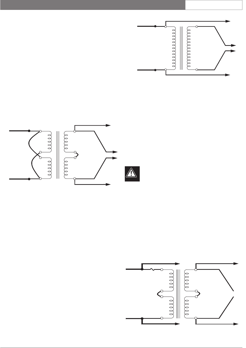
5.6.6 LTC 9384/50 Housings
These housings require connection to 230VAC, and are
designed for use where the site power is 230 volts.
The LTC 9384/50 Housings can easily be used with
either 230 volt or 24 volt cameras.
The internal transformer provides 24VAC for both the
heater and 24 volt camera power.
Do not remove the transformer insulator. No
user serviceable parts are present.
For 230 Volt Cameras:
1. Installing a 230 volt camera into the LTC 9384/50
housing requires the camera's line cord to be cut
and connected with the transformer's primary
wiring and the power supply line (see FIGURE 10).
2. The secondary flying leads (white/black striped)
will not be used in this application, and should be
taped to prevent shorting. See wiring diagram
FIGURE10 for clarification and FIGURE 5 for
power connection drawings.
FIGURE 10 LTC 9384/50 Transformer Wired for
230 Volt Camera
Black
24 VAC
Input
White
Red
24 VAC
White/
Black
Striped
To Heater/Defogger
Red
White/
Black
Striped
6
1
12
7
To Camera
To Heater/Defogger
Black
115 VAC
Input
White
Red
24 VAC
White/
Black
Striped
To Heater/Defogger
Red
White/
Black
Striped
6
5
2
1
12
11
8
7
To Camera
Brown
Connector Black
To Camera
To Heater/Defogger
To Heater/Defogger
No Connection
To Camera
B
lue
Connector
Blue
2
30 VAC
Input
24 VAC
White/
Black
Striped
White/
Black
Striped
6
5
1
2
12
11
8
7