


24 en | Installation DinionHD 1080p IP Camera
AM18-Q0600 | v1.0 | 2011.07 Installation Manual Bosch Security Systems
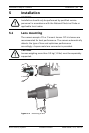
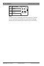
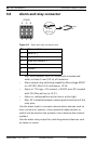
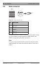
5.5 Alarm and relay connector
Figure 5.5 Alarm and relay connector pins
– Max. wire diameter AWG 22-28 for both stranded and
solid; cut back 5 mm (0.2 in) of insulation.
– Alarm output relay switching capability: Max voltage 30VAC
or +40 VDC. Max 0.5 A continuous, 10 VA.
– Alarm in: TTL logic, +5V nominal, +40 VDC max, DC coupled
with 22 kOhm pull-up to +3.3 V.
– Alarm in: configurable as active low or active high.
– Max. 42 V allowed between camera ground and each of the
relay pins.
Use the alarm input to connect external alarm devices such as
door contacts or sensors. A zero potential make-contact or
switch can be used as the actuator (use a bounce-free contact
system).
Use the alarm relay output for switching external devices such
as lamps or sirens.
Pin Alarm socket
1 Alarm in 1
2 Alarm in 2
3 Relay out contact 1
4Ground
5Ground
6 Relay out contact 2
Alarm
456
123
5 mm
(0.2 in)