


CHAPTER 4 IMAGE FORMATION SYSTEM
COPYRIGHT
©
1999 CANON INC. CANON PC800s/900s REV.0 AUG. 1999 PRINTED IN JAPAN (IMPRIME AU JAPON)
4-21
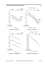
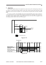
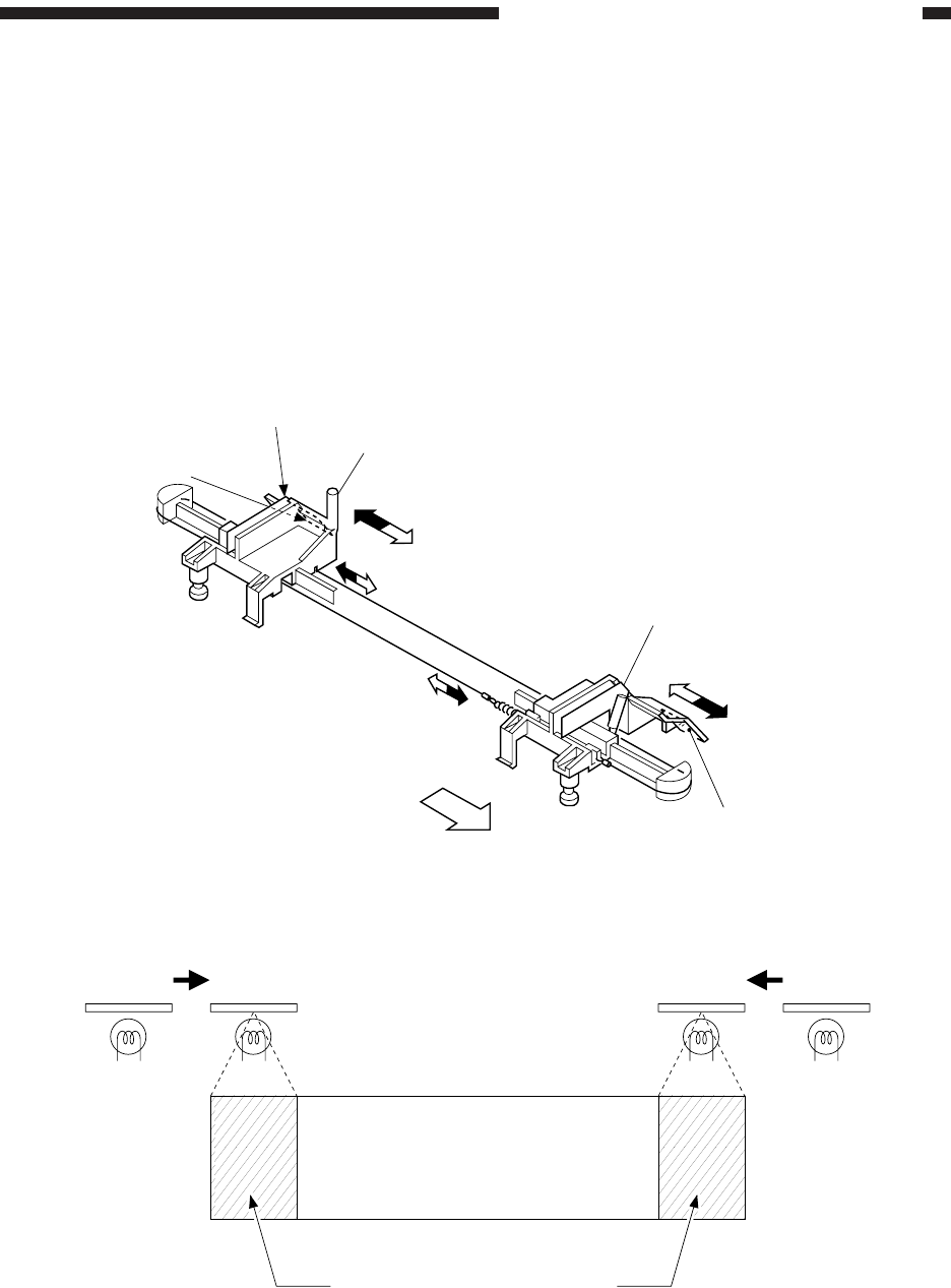
Figure 4-121
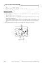
Figure 4-122
Reflecting
plate
Rear side
blanking lamp
Lens shift detecting shaft
Front side
blanking lamp
Reflecting
plate
(front)
AB
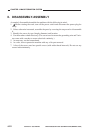
Photosensitive drum
Non-image area in Reduce mode
A: Position of the side blanking lamp in Direct and Reduce mode
B: Position of the side blanking lamp in Reduce mode
BA
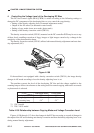
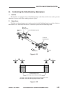
G. Controlling the Side Blanking Mechanism
1. Outline
The machine is equipped with a side blanking lamp at the front and the rear used to prevent
adhesion of excess toner when making reduced copies.
2. Operations
To blank out the non-image area in reduce mode, the side blanking lamp is moved in relation to
the distance over which the lens moves as detected by the lens shift detecting shaft.