


CHAPTER 8 ADF
COPYRIGHT
©
1999 CANON INC. CANON PC800s/900s REV.0 AUG. 1999 PRINTED IN JAPAN (IMPRIME AU JAPON)
8-3
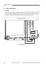
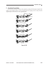
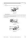
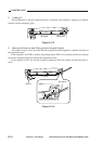
2. Inputs to and Outputs from the ADF Controller PCB
a. Inputs to and Outputs from the ADF Controller PCB (1/1)
Figure 8-103
ADF switch
Registration paper
sensor
Original placement
sensor
Delivery sensor
PI1
J105
J6-1
-2
ADF controller PCB
J5-1
J5-4
J5-7
-3
-2
-6
-5
-9
-8
J3-1
-2
+24V
MS1
ADFC When ADF is opened, '1'.
PDP1 When original is detected, '1'.
(when light-blocking plate is at sensor)
+5V
+5V
+5V
PDP2 When original is detected, '0'.
(when light-blocking plate is at sensor)
PDP3 When original is detected, '0'.
(when light-blocking plate is at sensor)
See p. 8-15.
M1
M2
Pickup motor
Belt motor
-3
-4
J3-6
-7
PI2
PI3
Serial communication
Copier
J2
See p. 8-14.
-5
*Negative logic.
J114
J202