


CHAPTER 4 IMAGE FORMATION SYSTEM
COPYRIGHT
©
1999 CANON INC. CANON PC800s/900s REV.0 AUG. 1999 PRINTED IN JAPAN (IMPRIME AU JAPON)
4-4
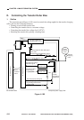
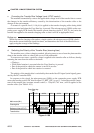
C. Controlling the Primary Charging Roller Bias
1. Outline
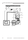
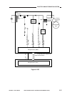
The circuit shown in Figure 4-103 is used to control the voltage applied to the primary charging
roller, and has the following functions:
• Turning on and off the DC/AC bias
• Controlling the DC bias to a specific voltage
• Controlling the AC bias to a specific voltage
• Switching the level of the DC bias
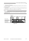
Both DC bias and AC bias are applied to the primary charging roller so as to ensure that the
surface potential of the photosensitive drum will be uniform. The level of the DC bias is switched
between when forming copy images and when not forming copy images.
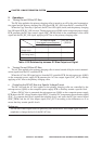
Reference:
DC component: -400 V (non-image area)/-625 V (image area)
AC component: 2000 Vpp to 3000 Vpp (885µA)