


CHAPTER 6 FIXING SYSTEM
COPYRIGHT
©
1999 CANON INC. CANON PC800s/900s REV.0 AUG. 1999 PRINTED IN JAPAN (IMPRIME AU JAPON)
6-6
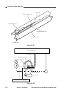
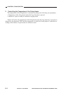
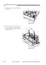
Figure 6-106
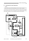
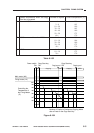
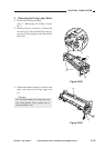
Figure 6-105
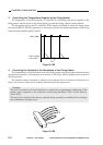
4. Correcting the Variation in the Resistance of the Fixing Heater
The characteristics of the flat heater used as the fixing heater vary from heater to heater because
the production method. A discrepancy in resistance, if left alone, will not enable correct control of
the fixing heater.
The machine makes correction in relation to the selected level of resistance (from three set-
tings), and corrects it basd on the readings obtained by the microprocessor.
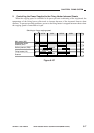
Caution:
The level of resistance of the fixing heater is selected by an appropriate combination of the
jumper wires connected to the connector of the fixing thermistor (TH1) and the delivery
sensor (PS3).
The best level is selected at the factory when the fixing assembly is assembled. Do not change
the combination of jumper wires.
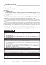
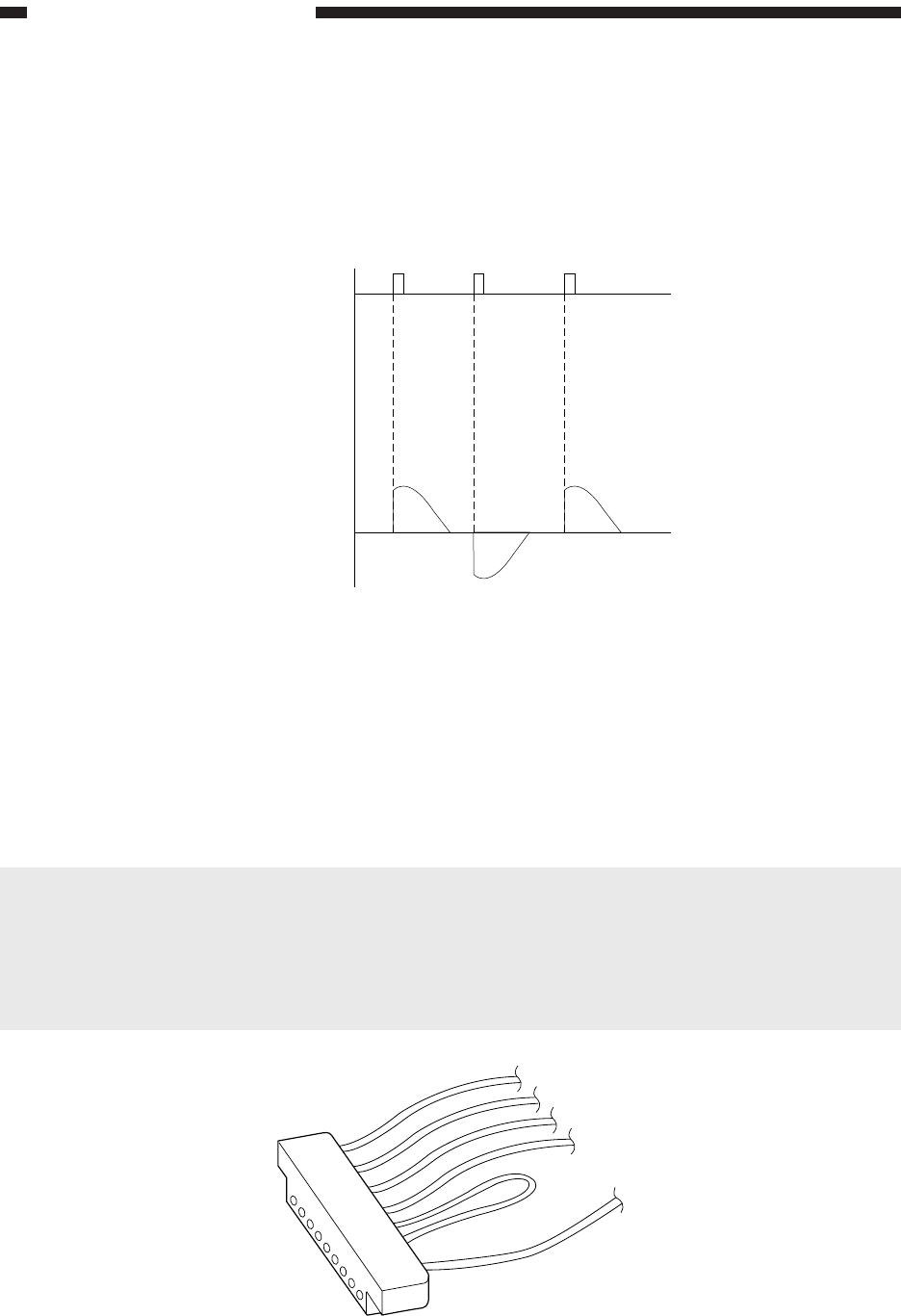
HEAT_PWM
Power supplied
to the heater
3. Controlling the Temperature Supplied to the Fixing Heater
The temperature of the fixing heater is controlled by controlling the power supplied to the
fixing heater, and the power to the fixing heater is controlled using a phase control method.
The microprocessor on the DC controller PCB controls the timing at which the fixing heater
duty signal (HEAT_PWM) is generated so that power suited to the target temperature of the fixing
heater may be supplied (phase control).