


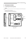

CHAPTER 3 EXPOSURE SYSTEM
COPYRIGHT
©
1999 CANON INC. CANON PC800s/900s REV.0 AUG. 1999 PRINTED IN JAPAN (IMPRIME AU JAPON)
3-10
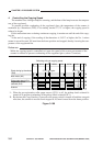
2. Operations
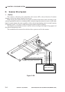
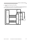
a. Turning On/Off the Scanning Lamp
The DC controller PCB and the composite power supply exchange signals in serial communi-
cation to control the scanning lamp. According to the scanner lamp active voltage signal, the mi-
croprocessor (Q900) on the composite power supply PCB controls the intensity adjustment signal
(PWM_1KHz) and the lamp activation signal (LAMP_ON) to turn on/off the scanning lamp
(LA1).
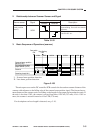
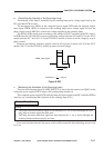
When LAMP_ON is ‘0’,
The phase control circuit turns on.
The arcing circuit turns on.
The scanning lamp turns on.
When LAMP_ON is ‘1’,
The phase control circuit turns off.
The arcing circuit turns off.
The scanning lamp turns off.