


CHAPTER 3 EXPOSURE SYSTEM
COPYRIGHT
©
1999 CANON INC. CANON PC800s/900s REV.0 AUG. 1999 PRINTED IN JAPAN (IMPRIME AU JAPON)
3-8
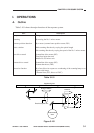
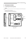
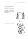
b. Operations
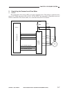
The microprocessor (Q101) mounted on the DC controller PCB receives instructions from the
control panel PCB copying mode settings (e.g., reproduction ratio). In response, it applies drive
pulses to the scanner/lens drive motor (M2) through the motor driver circuit.
The scanner motor is a 4-phase stepping motor, and changes the direction and speed of its
rotation according to the sequence and frequency of drive pulses (SC-A*through SC-B*).
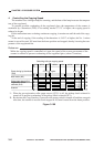
The motor drive voltage is switched on and off by pulse signals (A through B*) generated by
the microprocessor (Q101). Any of these pulse signals is generated when the motor is in operation,
while no pulse signal is generated when the motor is at rest.
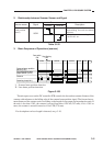
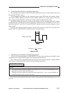
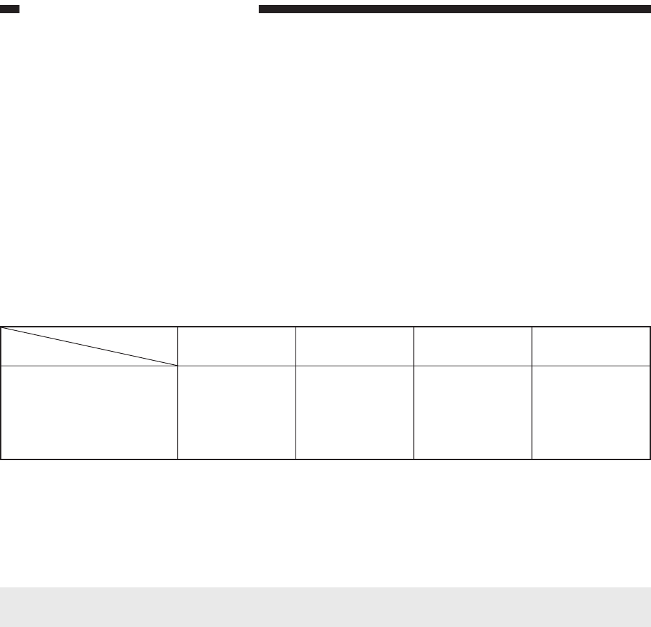
The current switching signals from 1 to 3 generated by the microprocessor (Q101) are used to
control the current flowing to the motor so that it varies according to the state of the scanner and the
lens.
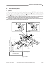
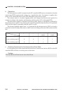
c. Detecting Overcurrent for the Scanner/Lens Drive Motor
If overcurrent flows to the scanner/lens drive motor for some reason, the fuse (R339) on the DC
controller PCB will blow to cut the power to the motor.
Caution:
The fuse (R339) will not recover once it has blown.
Forwarding the
scanner
1
1
1
Current switching signal 1
Current switching signal 2
Current switching signal 3
Starting the lens
0
0
0
Moving the lens
0
0
1
Reversing the
scanner
0
1
1