


CHAPTER 4 IMAGE FORMATION SYSTEM
COPYRIGHT
©
1999 CANON INC. CANON PC800s/900s REV.0 AUG. 1999 PRINTED IN JAPAN (IMPRIME AU JAPON)
4-17
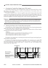
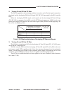
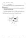
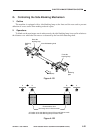
Figure 4-115
Copy Start key
ON
STBY INTR AER
SCFW SCFW
SCRV
LSTR
STBY
Main motor (M1)
Scanner / lens drive
motor (M2)
AE signal (AE)
Scanning lamp (LA1)
SCRV
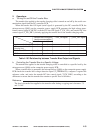
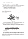
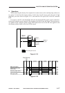
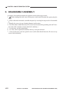
Figure 4-114
68.8mm
(approx.)
23.5mm
(approx.)
5.8mm
(approx.)
37.7mm
(approx.)
Middle of
original
: Area read by AE sensor
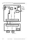
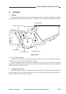
2. Operations
When measuring the density of an original, the scanner turns on the scanning lamp, and moves
to a point 115 mm from the home position. At this time, the AE sensor reads the level of light
reflected by the area shown in Figure 4-112, and sends the AE signal (AE) to the DC controller
PCB.
In response, the DC controller PCB sends the developing DCON signal (serial communica-
tion) to the composite power supply PCB according to the level of the AE signal. The microproces-
sor (Q900) on the composite power supply PCB controls the level of the DC bias applied to the
developing cylinder based on the level of this signal.