


CHAPTER 7 EXTERNALS/AUXILIARY MECHANISMS
COPYRIGHT
©
1999 CANON INC. CANON PC800s/900s REV.0 AUG. 1999 PRINTED IN JAPAN (IMPRIME AU JAPON)
7-3
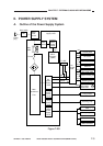
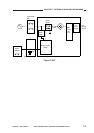
Figure 7-201
Power
plug
DS1
Composite power
supply circuit
Noise
filter
circuit
Door switch
Relay
RL601
FU102
Trans-
former
T600
Auxiliary
power
supply
circuit
+5V
Micro-
processor
(Q900)
Main
transformer
T101
Fixing
heater
control
circuit
DC
power
supply
circuit
Scanning
lamp
control
circuit
High-
voltage
power
supply
circuit
+24VR
+24VU
+5V
+5V
+24VR
+24VU
+24VU
+24VU
Control panel
AE sensor
+5V
Sensor
To ADF
Solenoid
Scanner/lens
drive motor (M2)
Blanking lamp
+24VU
+24VU
Scanner cooling fan
M1
Main motor/
main motor
driver PCB
Fixing heater
Primary charging
roller
Scanning lamp
Developing roller
Transfer roller
Static eliminator
DC
controller
PCB
II. POWER SUPPLY SYSTEM
A. Outline of the Power Supply System