


CHAPTER 8 ADF
COPYRIGHT
©
1999 CANON INC. CANON PC800s/900s REV.0 AUG. 1999 PRINTED IN JAPAN (IMPRIME AU JAPON)
8-2
B Basic Construction
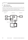
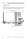
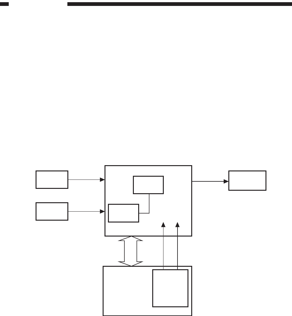
1. Outline of the Electric Circuitry
The ADF’s major electrical mechanisms are controlled by the CPU on the ADF controller
PCB.
The CPU on the ADF controller PCB reads the signals from the sensors and the copier and
generates signals to drive the motor at such times as programmed in advance.
The copying modes selected on the copier are communicated to the ADF in serial, and the ADF
communicates to the copier the state of feeding originals to the copier in serial. (It does not use an
IC for communications.)
Figure 8-102
Serial communication
Copier
Composite
power
supply
PCB
24V
5V
ROM
(Q2)
CPU
(Q1)
Switch
Sensor
ADFcontroller PCB
Motor
[Output block][Control block]
[Input block]