


COPYRIGHT
©
1999 CANON INC. CANON PC800s/900s REV.0 AUG. 1999 PRINTED IN JAPAN (IMPRIME AU JAPON)
11-62
CHAPTER 11 TROUBLESHOOTING
11-62
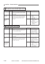
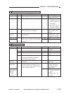
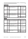
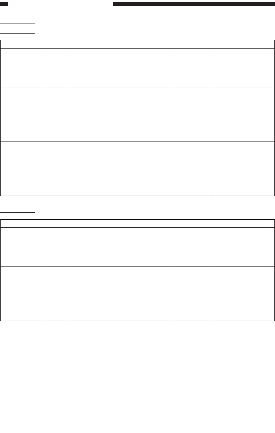
2 E000
YES/NO
NO
NO
YES
YES
NO
Cause
Thermistor
(TH1)
Heater,
Fuse (FU2)
Thermistor
(TH1)
Composite
power
supply PCB
DC control-
ler PCB
Step
1
2
3
4
Checks
Are the connection of J102 on the DC
controller PCB and the wiring to the
thermistor (TH1) normal?
Is there electrical continuity between
J207-1 and -2 on the fixing heater
side?
Replace the fixing upper unit. Is the
problem corrected?
Replace the composite power supply
PCB. Is the problem corrected?
Action
Correct the connection
of J102 on the DC
controller PCB and the
wiring to the ther-
mistor (TH1).
Check the wiring from
the composite power
supply PCB to the
fixing heater; if
normal, replace the
fixing assembly upper
unit.
End.
End.
Replace the DC
controller PCB.
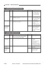
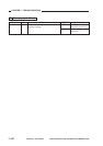
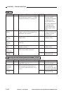
3 E001
YES/NO
NO
YES
YES
NO
Cause
Thermistor
(TH1)
Thermistor
Composite
power
supply PCB
DC control-
ler PCB
Step
1
2
3
Checks
Are the connection of J102 on the DC
controller PCB and the wiring to the
thermistor (TH1) normal?
Replace the fixing assembly upper
unit. Is the problem corrected?
Replace the composite power supply
PCB. Is the problem corrected?
Action
Correct the connection
of J102 on the DC
controller PCB and the
wiring to the ther-
mistor (TH1).
End.
End.
Replace the DC
controller PCB.