


CHAPTER 2 BASIC OPERATION
COPYRIGHT © 1999 CANON INC. CANON PC800s/900s REV.0 AUG. 1999 PRINTED IN JAPAN (IMPRIME AU JAPON)
2-9
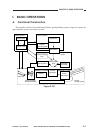
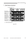
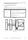
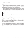
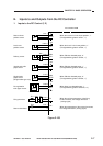
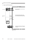
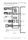
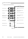
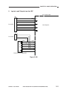
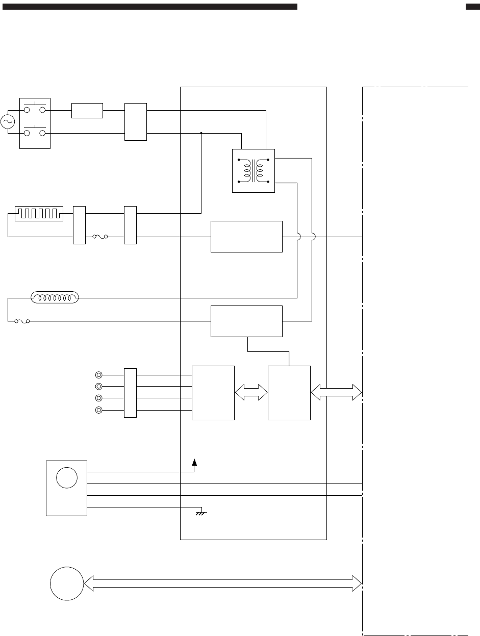
3. Outputs from the DC Controller (1/2)
Figure 2-107
J201-2
-1
DC controller PCBComposite power supply PCB
Noise filter
+24V
HVT board
High-
voltage
circuit
block
Micro-
processor
DS1
Door switch
Transformer
Line filter
(220/240V model only)
M2
Scanner/
lens drive motor
M1
Main
motor
Main motor
driver PCB
NF1
LF1
J207-1
-2
J104-2
FU1
Fixing heater
H1
J434J16
Fixing heater
activation circuit
J910-3
-1
J103-6
J104-1
Scanning lamp
LA1
Scanning lamp
activation circuit
FU2
Thermal fuse 1
Thermal fuse 2
HEAT_TRG
Communication with
the composite power
supply
MMD
MLOCK
See p. 3-7.
When ‘0’,
the fixing heater
turns on.
See p. 2-5.
Primary charging roller
Developing cylinder
Transfer charging roller
Static eliminator