


CHAPTER 11 TROUBLESHOOTING
COPYRIGHT
©
1999 CANON INC. CANON PC800s/900s REV.0 AUG. 1999 PRINTED IN JAPAN (IMPRIME AU JAPON)
11-47
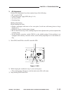
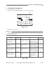
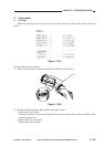
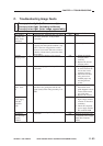
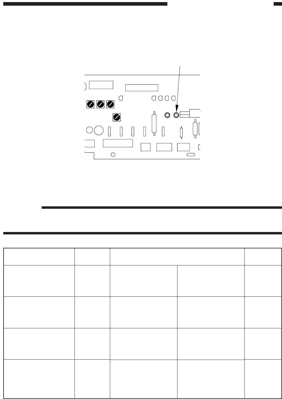
5. Checking the Photointerrupters
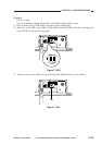
1) Set the meter range to 12 VDC.
2) Connect the - probe to GND (CPGND1) on the DC controller PCB.
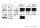
Figure 11-271
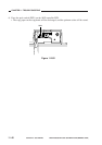
3) Make checks as instructed.
Reference:
The photointerrupers other than those shown in Table 11-209 are connected in a matrix, hence
the omission from the table.
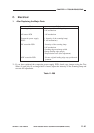
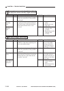
Table 11-208
Sensor
PS1
Scanner home position
sensor (SCHP)
PS2
Lens home position sen-
sor (LHP)
PS4
Vertical path roller pa-
per sensor (PDP)
Q751
Pre-registration roller
paper sensor (RPD)
Checks
During standby, move
the scanner by hand.
During standby, move
the lens mount by
hand.
During standby, move
the detecting lever by
hand.
During standby, move
the detecting lever by
hand.
When the light-block-
ing plate is at PS1,
When the light-block-
ing plate is not at PS1,
When the light-block-
ing plate is at PS2,
When the light-block-
ing plate is not at PS2,
When the light-block-
ing plate is at PS4,
When the light-block-
ing plate is not at PS4,
When the light-block-
ing plate is at Q751,
When the light-
blocking plate is not at
Q751,
Connector
J101-3
J109-10
J132-5
J108-3
Voltage
(approx.)
5V
0V
5V
0V
5V
0V
0V
5V
GND
VR106
VR107
VR104
VR105
CPGND1
CP23