


CHAPTER 3 EXPOSURE SYSTEM
COPYRIGHT
©
1999 CANON INC. CANON PC800s/900s REV.0 AUG. 1999 PRINTED IN JAPAN (IMPRIME AU JAPON)
3-3
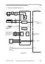
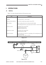
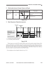
Figure 3-103
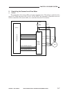
Lens home position
sensor (PS2)
Lens shift detecting shaft
for side blanking lamp
Lens unit
Reduction
Scanner/lens drive motor
(M2)
No. 4/5 mirror unit
Top View
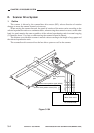
Switching gear
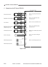
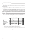
While the lens is moving
Lens home position detection
signal(LHP)
Lens solenoid drive signal(LNSLD*)
SL3
DC controller PCB
SL3 SL3
ON OFF
Switching
gear
Switching
gear
Enlargement
Cam
Lens cable
While the scanner is moving
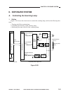
C. Lens Drive System
1. Outline
The lens drive system is driven by the scanner/lens drive motor (M2). When the lens solenoid
(SL3) turns on, the switching gear is pushed in the direction of
. In this condition, when the
scanner/lens drive motor rotates in reverse direction (
), the lens unit will move in the direction of
reduction (
) by the work of the gear and the lens cable.
At the same time, the No. 4/5 mirror unit operates according to the distance over which the lens
unit is moved by the work of the gear and the cam, thereby varying the optical length.
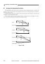
At this time, the blanking lamp also moves in conjunction with the lens to blank out the appro-
priate front/rear widths to suit the selected reduction ratio.