


CHAPTER 2 BASIC OPERATION
COPYRIGHT © 1999 CANON INC. CANON PC800s/900s REV.0 AUG. 1999 PRINTED IN JAPAN (IMPRIME AU JAPON)
2-5
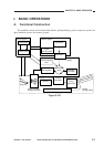
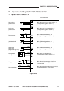
D. Controlling the Main Motor (M1)
1. Outline
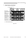
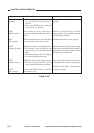
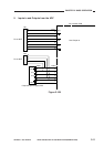
Table 2-102 shows the functions of the main motor control circuit, and Figure 2-104 is a block
diagram of the circuit.
Table 2-102
Figure 2-104
Composite
power
supply
PCB
DC
controller
PCB
Phase
control
drive
circuit
Reference signal
Drive
current
Hall IC output
MMCLK
Clock pulse
generator
Main motor
(M1)
Main motor drive PCB
J205
-4
-3
-2
-1
+24V
J901
-1
-2
-3
-4
J103
-6
J203
-3
J104
-1
J204
-7
24V
GND
MMD
MLOCK
Item
Power supply
Drive signal
Moving/drive parts
Control
Error detection
Description
24 VDC from the composite power supply.
Signal (MMD) from the DC controller PCB.
Photosensitive drum, primary charging roller, developing assembly,
transfer charging roller, pickup roller, vertical roller, registration roller,
feeding assembly, fixing assembly, delivery roller, heat exhaust fan
Executes on/off control.
Executes constant speed rotation control.
Issues ‘E010’.