


Focus/Zoom Control Interface Crestron CNXFZ
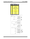
NOTE: All network wiring must consist of two twisted-pairs. One twisted pair is
the +24V conductor and the GND conductor and the other twisted pair is the Y
conductor and the Z conductor.
NOTE: When daisy-chaining Cresnet units, strip the ends of the wires carefully to
avoid nicking the conductors. Twist together the ends of the wires that share a pin on
the network connector, and tin the twisted connection. Apply solder only to the ends
of the twisted wires. Avoid tinning too far up the wires or the end becomes brittle.
Insert the tinned connection into the Cresnet connector and tighten the retaining
screw. Repeat the procedure for the other three conductors.
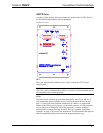
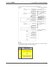
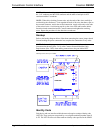
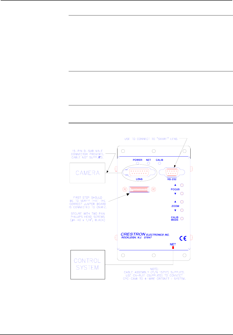
Hookup
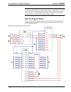
Refer to the hookup diagram below. Other than connecting the correct jumper board
first and making the power connection last, complete the connections in any order.
NOTE: Before making any connections, review latest revision of network
interconnection drawing (Doc. 5411) or the Crestron Network Modular Cable
Requirements (Doc. 5682) when making connections to the port labeled NET.
Hookup Connections for CNXFZ
CNXFZ
Identity Code
Each device and user interface within the network requires a unique identity code
(NET ID). These codes are recognized by a two-digit hexadecimal number from 03
to FE. The NET ID of the unit must match an identity code specified in the SIMPL
8 • CNX Focus/Zoom Control Interface: CNXFZ Operations Guide - DOC. 5753